
LM-79 Moving Detector Goniophotometer (Mirror Type C)
LSG-6000

High Precision Rotation Luminaire Goniophotometer
LSG-1890B

High Precision Rotation Luminaire Goniospectroradiometer
LSG-1890BCCD

Goniophotometer for Automotive and Signal Lamps
LSG-1950

Goniophotometer for Traffic Signal Lamps
LSG-1950S

Compact Goniophotometer
LSG-1200A

Near Field Moving Detector Goniophotometer
LSG-1900B
Select an organization
to browse standards
EMC conducted emissions testing is one of the starting activities in the contemporary compliance and product development laboratories. It measures unwanted radio frequency energy that travels on line of power and signal instead of traveling through free space. Practically, EMI test of conducted phenomena involves identifying whether a device emits a back injection into the mains or other linked cables to such level that it may cause a disruption on other equipment. With the proliferation of high-speed digital interfaces and semiconductors with wide band operations switching power, adding to the difficulties of controlled conducted emissions has become more difficult and more critical. To use the test correctly involves something beyond setting up of instruments. It requires rigorous establishment of regular steps that can be repeated and knowledgeable use of findings.
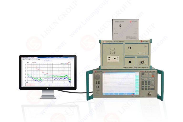
A contemporary configuration of conducted emissions is constructed on controlled impedance space. Line Impedance Stabilization Network This is the key element in this chain since it provides a specified impedance to the equipment under test and isolates it off of external noise on the supply. The LISN also offers a constant measuring port which passes the disturbance voltages to either a spectrum analyzer or receiver. LISN ratings should be chosen based on the supply voltage current and frequency without compromising the standard that should be used.
The detector and dwell time that should be supported by receiver or analyzer must be in line with the standard applied. Peak quasi peak and average detectors display varied features of the behavior of interference hence all the three are normally necessary. Preamplifiers are occasionally added with an aim of increasing sensitivity but should be chosen thoughtfully in order to prevent overload. Interconnecting LISN and recipient should be short, well shielded and routing repeatable to prevent pickup and variation.
Ground reference is as well vital. As required, the reference ground plane should be continuous and connected to the LISN and equipment chassis. Any distortion causes impedance variations that distort the levels of measurement. In new laboratories, standard cable tray benches and bonding straps are invested in such that starting each test at a common baseline.

Prior to conducting an EMI test, the device under test should be set up to come up with worst case operating conditions. This incorporates power mode loads peripheral connections and software states. Converters with switching To achieve high spectral content In the case of converters and motor drives where switching strongly depends on operating point then engineers ought to make use of the maximum possible switching activity by making use of duty cycles and loading. Warm up time is important since switching edges are dependent on component temperature and hence emission.
When the operator is running the test, he monitors the noise behavior over a period of time and scans through the required frequency range. Contemporary receivers also support time domain visualizations which can be used to align the activity of devices with emission. In case of the presence of the suspect peak then it is advised to re measure it using the corresponding detector and dwell time to allow assessment of compliance. Noted configuration settings are a prerequisite since minor modifications can alter the results by a few decibels.
Execution discipline involves environmental noise control. Tests that have been conducted are vulnerable to background noise in the form of the lighting of laboratories and machinery around. Create a background noise test where the device is off and attached to the device to ensure sufficient margin. In case of margin un-sufficiency, it should be ensured that noises are reduced.
The pattern of frequency domain and circuit topology are needed in the interpretation of conducted emission data. Fast switching edges or bad filtering is likely to be the cause of broadband noise, whereas clock leakage or resonance might be the cause of discrete lines. The comparison of phase and neutral measurements can indicate the presence of common mode versus differential mode dominance that can inform the mitigation strategy.
Time domain information is potently correlated. It is useful in getting causal relations by triggering the receiver on certain operating events like load changes. Without causing product disassembling, sources can be localized on power paths by near field probing. Hypotheses are confirmed by iteration testing using temporary mitigation elements like ferrites, capacitors before design changes are implemented.
Standards are a definition of limits, engineering judgment only a definition of acceptable margin. A only slightly good product can fail in the production variance or in some other installation. Contemporary laboratories are thus seeking margin and written uncertainty. Raw data makes it possible to re-analyze, should any of the standards change, or the variant of a product is added.
There is no phase of conducted emissions testing that exists in isolation. It contributes into design reviews corrective action circle and official compliance reports. The combination of the test software and data management systems guarantees traceability and repeatability in projects. Test scripting Automated test scripts minimize variability in operators and accelerate regression testing of design variations.
The compatibility of equipment ecosystem. The LISN units receivers and software are supposed to be compatible with each other. The suppliers like LISUN have many laboratories that source coordinated systems due to the ease of maintenance and audit with consistent interfaces and calibration support. No matter how a system is legitimized through periodic verification of suppliers with reference sources.
Another final but an important aspect is training. The operators should be aware not just how to take the test, but also why each of the steps is important. Continuous process of revising failed cases and root cause analyses develop institutional knowledge which enhance efficiency and improve result.
The structured infrastructure disciplined practice and informed analysis of EMC conducted emissions testing is needed to get good use in the modern lab. This is based on a properly designed system that is developed around stable ground amplifying conditions of the accurate receivers in addition to controlled grounding facilities. Close engineering realistic operating conditions and astute data interpretation cause measurements to become engineering wisdom. Once designed into a larger compliance mechanism and backed by dependable equipment and training provided emissions testing is no longer a last minute obstacle to the EMI test process, but an active design tool.
Tags:EMI-9KB
LISUN’s Motor-Operated Tool | Power Tool Testing solutions strictly comply with a range of core international standards, providing full support for safety and electromagnetic compatibility (EMC)...

LISUN’s transformer test solutions meet IEC 61558-1, IEC 60076-1, IEC 62041 standards. Covering safety, performance, EMC tests, ensuring transformers comply with global requirements.

LISUN’s household and appliance switch testing solutions meet IEC 60669, IEC 61058, IEC 62271 standards. Covering electrical, mechanical & EMC tests for global compliance.

For the CFL design and manufactory, LISUN can supply a full quality control test solution, including photometric, colorimetric, electricity, flicker, IES candela distribution, surge test, electrical...

 中文简体
中文简体
