
LM-79 Moving Detector Goniophotometer (Mirror Type C)
LSG-6000

High Precision Rotation Luminaire Goniophotometer
LSG-1890B

High Precision Rotation Luminaire Goniospectroradiometer
LSG-1890BCCD

Goniophotometer for Automotive and Signal Lamps
LSG-1950

Goniophotometer for Traffic Signal Lamps
LSG-1950S

Compact Goniophotometer
LSG-1200A

Near Field Moving Detector Goniophotometer
LSG-1900B
Select an organization
to browse standards
Abstract:Understanding what causes a voltage spike is fundamental to designing robust electronic systems and ensuring their electromagnetic compatibility (EMC). Voltage spikes, also known as transients or surges, are brief, high-energy disturbances that can degrade insulation, corrupt data, or cause catastrophic failure in electrical and electronic equipment. This paper examines the primary physical origins of voltage spikes, including inductive load switching, lightning strikes, and power line faults. It then reviews the key international standards that define spike waveforms and test levels, with particular focus on RTCA DO-160 Section 17 for airborne equipment.
The paper analyzes the technical parameters that characterize spikes—rise time, duration, amplitude, and impedance—and discusses engineering design requirements for spike generation equipment. Finally, it examines a practical implementation, the LISUN DO160-S17 Voltage Spike Generator, which complies with DO-160 Section 17 and offers a 5 V to 1000 V continuously adjustable output with ≤2 μs rise time, illustrating how modern instrumentation enables precise, repeatable transient testing.
Voltage spikes are ubiquitous in electrical power systems and can originate from both external and internal sources. Understanding what causes a voltage spike is the first step toward developing effective protection strategies and compliance test plans. Externally, lightning strikes induce high-energy surges into power and communication lines. Internally, the sudden interruption of current in an inductive load—such as a relay, motor, or transformer—generates a counter-electromotive force that can reach several times the nominal system voltage. Power line faults, such as short circuits or capacitor bank switching, also produce transient overvoltages. Given the potential for damage and malfunction, regulatory bodies have established standardized test waveforms and procedures to verify equipment immunity. This paper explores the physical mechanisms behind voltage spikes, the relevant standards, and the engineering principles of equipment designed to simulate them for compliance testing.

DO160-S17 Voltage Spike Generator
RTCA DO-160, “Environmental Conditions and Test Procedures for Airborne Equipment,” is the definitive standard for civil aviation equipment. Section 17 specifically addresses voltage spikes impressed on equipment power input lines. The standard defines a unidirectional spike waveform with a fast rise time (≤2 μs) and a specific duration and energy content. It requires application of both positive and negative polarity spikes at a repetition rate of up to 2 Hz, directly onto the ungrounded input power supply lines of the equipment under test (EUT). Compliance with DO-160 Section 17 is mandatory for virtually all electrical equipment installed in aircraft.
While DO-160 Section 17 is the focus for aviation, other industries reference similar transient waveforms:
Despite differences in waveform parameters, all these standards share the goal of replicating what causes a voltage spike in real-world environments to ensure equipment robustness.
The fundamental principle behind what causes a voltage spike from inductive loads is Faraday’s Law of Induction. The voltage across an inductor is given by V = L ⋅ d i / d t V=L⋅di/dt, where L L is inductance and d i / d t di/dt is the rate of change of current. When a switch interrupts current flow through an inductor (e.g., a relay coil), the magnetic field collapses rapidly, inducing a high voltage that attempts to maintain current. This “inductive kickback” can generate spikes many times the supply voltage, with rise times in the nanosecond to microsecond range depending on stray capacitance and circuit impedance.
Standardized test spikes are defined by four key parameters:
Rise Time ( t r t r ): The time for the voltage to rise from 10% to 90% of its peak value. DO-160 Section 17 specifies t r ≤ 2 μ s t r ≤2μs, which challenges the bandwidth of both protection devices and test generators.
Pulse Duration ( t d t d ): The time at half-maximum amplitude. For DO-160, the duration must exceed 10 μs, ensuring sufficient energy is delivered to stress the EUT.
Peak Amplitude ( V p k V pk ): The maximum voltage. DO-160 test levels range from 50 V to 600 V depending on the equipment category and power line type.
Source Impedance: The internal impedance of the generator, which determines the current available during the spike. DO-160-compliant generators, such as the LISUN DO160-S17, use a 50 Ω ± 10% impedance to standardize the energy delivered.
To apply spikes safely to an EUT without damaging auxiliary equipment, a coupling/decoupling network (CDN) is essential. The CDN couples the spike onto the power line while decoupling the transient from the mains supply, preventing it from propagating back into the laboratory’s power distribution. The LISUN DO160-S17 incorporates a built-in single-phase CDN rated at AC 440 V / 16 A, allowing direct connection to the EUT’s power input. This integration simplifies test setup and ensures consistent coupling characteristics.
Designing a voltage spike generator that meets DO-160 Section 17 demands careful attention to high-voltage, fast-transient circuits. Key design elements include:
High-Voltage Pulse Forming Network (PFN): The PFN stores energy and shapes it into the required waveform. It typically consists of a charged capacitor discharged through a shaping inductor and resistor to control rise time and duration.
Fast Switching Element: To achieve ≤2 μs rise times, the switch must transition from off to on in nanoseconds. Modern generators use high-voltage solid-state switches (e.g., MOSFETs or IGBTs in series) or mercury-wetted relays for their low inductance and fast action.
Precision Control and Measurement: Generating a continuously adjustable output from 5 V to 1000 V with high accuracy requires a stable DC power supply, precise voltage sensing, and feedback control. The DO160-S17 achieves this with linear adjustment, ensuring the set voltage is accurately reproduced.
Impedance Matching: The 50 Ω ± 10% output impedance must be maintained throughout the pulse to deliver the specified waveform to the EUT. This requires careful PCB layout and component selection to minimize parasitic inductance and capacitance.
Built-in CDN: The CDN must handle the full spike voltage and current without distortion. It uses high-voltage capacitors for coupling and inductors to block the spike from reaching the mains, all while passing the 16 A power frequency current.
The LISUN DO160-S17 Voltage Spike Generator is designed specifically to meet the requirements of RTCA DO-160 Section 17 and MIL-STD-704. Its key specifications, derived from the product documentation, are summarized in Table 1.
Table 1. LISUN DO160-S17 Technical Specifications
| Parameter | Specification |
| Test Voltage Range | 5 V – 1000 V (continuously adjustable) |
| Rise Time | ≤2 μs |
| Pulse Duration | >10 μs |
| Output Impedance | 50 Ω ± 10 % |
| Output Polarity | Positive and negative |
| Trigger Mode | Automatic |
| Pulse Frequency | Max 2 Hz |
| Built-in CDN | Single phase, AC 440 V / 16 A |
The generator operates on an Android-based platform, providing a modern user interface for setting parameters, storing test sequences, and logging results. The built-in single-phase CDN simplifies test setups for most airborne equipment, which typically operates from 115 VAC or 28 VDC supplies. For equipment requiring different power configurations, external CDNs can be used.
In a typical test, the EUT is powered through the DO160-S17’s internal CDN. The generator automatically applies spikes at the selected amplitude and polarity, with a repetition rate up to 2 Hz as required by the standard. The engineer observes the EUT for any malfunction or degradation during and after the test. The generator’s precise control and repeatable waveform ensure that test results are reliable and comparable across different laboratories.
When selecting a generator for voltage spike testing, engineers should consider several factors beyond basic standard compliance:
Understanding what causes a voltage spike—from inductive load switching to external events like lightning—is essential for designing robust electronic systems and selecting appropriate immunity test methods. Standards such as RTCA DO-160 Section 17 provide a framework for simulating these real-world transients in a controlled, repeatable manner. The technical parameters of spike waveforms—rise time, duration, amplitude, and impedance—directly influence the stress applied to equipment and must be precisely controlled by test generators. Modern instruments like the LISUN DO160-S17 embody these engineering principles, offering a compliant, user-friendly solution for verifying the immunity of airborne equipment to voltage spikes. By using such tools, manufacturers can confidently certify their products for the demanding electrical environments they will encounter in service.
Tags:DO160-S17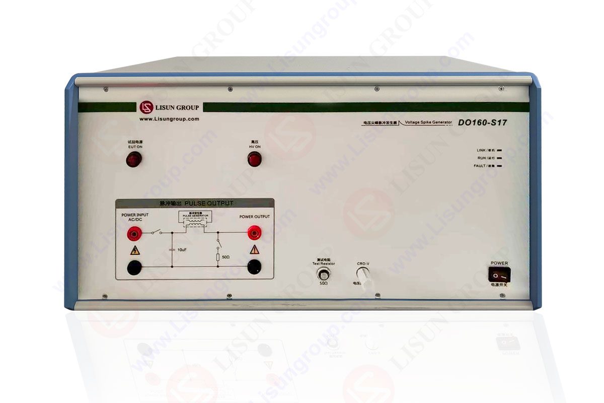

 中文简体
中文简体