LM-79 Moving Detector Goniophotometer (Mirror Type C)
LSG-6000

High Precision Rotation Luminaire Goniophotometer
LSG-1890B

High Precision Rotation Luminaire Goniospectroradiometer
LSG-1890BCCD

Goniophotometer for Automotive and Signal Lamps
LSG-1950

Goniophotometer for Traffic Signal Lamps
LSG-1950S

Compact Goniophotometer
LSG-1200A

Near Field Moving Detector Goniophotometer
LSG-1900B
Select an organization
to browse standards
NOTE: Fully recessed socket-outlets that comply with Clause 3.6.4 are deemed to comply with Clauses 3.8.1 and 3.8.2.
At any stage during normal insertion of a non-insulated pin plug into a socket-outlet, with the faces of the plug and socket-outlet in parallel planes, it shall not be possible to touch, with the standard test finger (see AS/NZS 3100), a pin that may become alive.
Socket-outlets, for use with two-pin flat-in plugs of the type shown in Figure 2.1(b), shall be checked for conformance with this requirement by means of an appropriate test plug having the minimum diameter of face and maximum length of live pins shown in
Figure 2(b).
Socket-outlets for use with three-pin flat pin plugs of the type shown in Figure 2.1(a) and Figure 2.1(d), and two-pin flat pin plugs of the type shown in Figure 2.1(c) and Figure 2.1(d), shall be checked for conformance with this requirement by means of an appropriate test plug having the dimensions shown in Figure C1 of Appendix C.

Three-Pin Test Plug for Checking Three-Pin Flat-Pin 250 V Max. Socket-Outlets Against The Standard Test Finger with AS/NZS 3112 Figure C1
Socket-outlets for use with three-pin plugs of the type having two flat live pins and one round earth pin, or two round live pins and one flat earth pin, as shown in Figure 2.1(f) and Figure 2.1(g), shall be checked for conformance with this requirement by means of the appropriate test plug having the dimensions shown in Figure G1(a) or Figure G1(b) of Appendix G, respectively.
For socket-outlets with covers that are intended to be removed for interchangeability, this test shall be conducted with and without the cover in position.
The design and construction of a socket-outlet shall be such that it is not possible for any pin of a plug with which the socket-outlet may appropriately be used to touch a live contact except during normal insertion, i.e. with each pin entering or adjacent to the aperture for the appropriate contact.
Socket-outlets for use with two-pin flat pin plugs of the type shown in Figure 2.1(b) shall be checked for conformance with this requirement by means of an appropriate test plug having the minimum diameter of face and maximum length of live pins shown in Figure 2.1(b).
Socket-outlets for use with three-pin flat pin plugs of the type shown in Figure 2.1(a) and Figure 2.1(d), and two-pin flat pin plugs of the type shown in Figure 2.1(c) and Figure 2.1(d), shall be checked for conformance with this requirement by means of an appropriate test plug having the dimensions shown in Appendix D.
NOTE: This provision is intended to prevent the insertion of one pin of a plug while the other pin or pins are overhanging the socket-outlet, and to prevent the insertion of an earthing pin in a live contact.
For socket-outlets with covers that are intended to be removed for interchangeability, this test shall be conducted with and without the cover in position.
The socket-outlet shall incorporate positive means to preclude incorrect assembly and to ensure that the plug pin apertures in the socket-outlet faceplate will always be aligned with the appropriate contacts of the socket-outlet.
Tags:GNGPL-31C1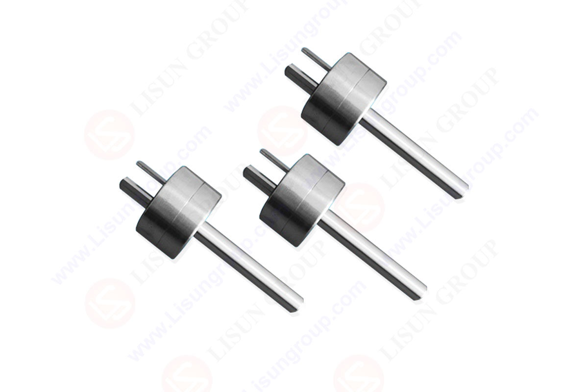

 中文简体
中文简体