LM-79 Moving Detector Goniophotometer (Mirror Type C)
LSG-6000

High Precision Rotation Luminaire Goniophotometer
LSG-1890B

High Precision Rotation Luminaire Goniospectroradiometer
LSG-1890BCCD

Goniophotometer for Automotive and Signal Lamps
LSG-1950

Goniophotometer for Traffic Signal Lamps
LSG-1950S

Compact Goniophotometer
LSG-1200A

Near Field Moving Detector Goniophotometer
LSG-1900B
Select an organization
to browse standards
To test light intensity with laboratory-grade precision requires systematic compliance with international photometric standards and advanced goniophotometric instrumentation. This paper presents a comprehensive technical analysis of five critical measurement parameters—luminous intensity distribution, zonal luminous flux, luminaire efficiency, luminance limitation, and spatial color uniformity—essential for accurate solid-state lighting characterization. By examining the engineering principles of Type C goniophotometer systems, particularly the mirror-based moving detector architecture, we elucidate the methodological framework specified in LM-79-19 and CIE-121 standards.
The analysis covers optical system design, angular measurement accuracy, detector calibration protocols, and darkroom environmental requirements necessary for repeatable photometric assessments. Furthermore, this study evaluates the systematic approach to mitigating measurement uncertainties through precise angular positioning (0.05° accuracy) and thermally stabilized detection systems, providing engineers with definitive technical criteria for selecting appropriate photometric instrumentation in industrial and research applications.
Accurate photometric characterization forms the fundamental basis for luminaire performance validation, energy efficiency certification, and lighting quality assurance in modern architectural and industrial applications. As solid-state lighting technologies continue to evolve in complexity and output intensity, the demand for standardized, reproducible methodologies to quantify luminous performance has become increasingly critical. The process to test light intensity extends beyond simple illuminance measurement, encompassing sophisticated spatial distribution analysis, angular luminous intensity mapping, and spectral radiant flux characterization under controlled laboratory conditions.
Contemporary photometric testing requires compliance with internationally recognized standards that define precise geometric configurations, detector specifications, and measurement protocols. The LM-79-19 standard, published by the Illuminating Engineering Society (IES), establishes the authoritative methodology for optical and electrical measurements of solid-state lighting products, mandating the use of Type C goniophotometer systems for comprehensive luminous intensity distribution measurements. This paper examines the technical foundations, engineering requirements, and systematic methodologies necessary to test light intensity with metrological precision.
The LM-79-19 standard (“Optical and Electrical Measurements of Solid-State Lighting Products”) represents the current definitive protocol for photometric characterization of LED-based luminaires, lamps, and modules. This standard explicitly specifies Type C goniophotometry as the required methodology for measuring luminous intensity distribution, particularly emphasizing the moving detector configuration with mirror-based light path maintenance. The standard requires that the luminaire under test remains stationary in its designated burning position throughout the measurement sequence, ensuring that thermal equilibrium and mechanical orientation do not compromise measurement validity.
Complementing LM-79-19, the CIE-121 publication (“The Photometry and Goniophotometry of Luminaires”) provides the theoretical foundation for angular measurement geometries, defining the C-plane coordinate system essential for spatial photometric mapping. These standards collectively mandate specific angular sampling intervals, detector spectral responsivity matching the CIE V(λ) function, and strict environmental controls including darkroom conditions with ambient light levels below 0.001 lux to prevent stray light interference during sensitive intensity measurements.
EN13032-1 clause 6.1.1.3 Type 4 requirements further refine the specifications for high-accuracy goniophotometric systems, establishing tolerances for angle positioning (typically ±0.05°), photometric distance ratios (minimum 10:1 for far-field measurements), and detector linearity (Class L according to DIN5032-6/CIE Pub. No. 69). For comprehensive characterization, modern testing protocols integrate spectral radiometry with traditional photometry, enabling simultaneous measurement of correlated color temperature (CCT) spatial distribution, color rendering indices, and photosynthetically active radiation (PAR) metrics critical for horticultural lighting applications.
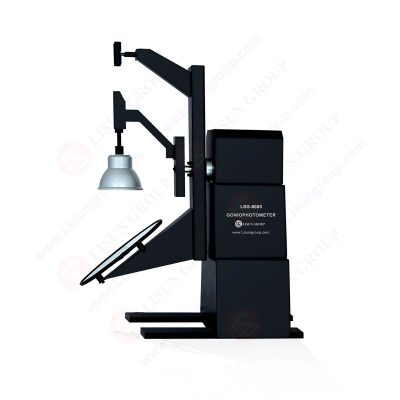
The Type C goniophotometer architecture operates on the principle of maintaining constant photometric distance while varying the angular orientation between the luminaire and detector. In the mirror-type configuration, a large plane mirror rotates synchronously with the photodetector around the stationary luminaire, directing luminous flux from the source to the detector while preserving the required measurement distance. This geometry eliminates the mechanical and thermal instability associated with rotating the luminaire itself, which is particularly critical for SSL products exhibiting significant heat dissipation characteristics.
The angular coordinate system employs C-planes (vertical planes through the photometric center) and γ angles (elevation from nadir), enabling comprehensive 4π steradian mapping of luminous intensity. High-precision systems utilize rotary motors with 0.001° angular resolution and absolute encoding systems to ensure repeatable positioning accuracy within 0.05°, essential for calculating derived metrics such as beam angle, field angle, and utilization coefficients used in lighting design software.
Photometric detection systems must exhibit spectral responsivity closely matching the CIE photopic luminosity function V(λ) with Class L precision (f1′ ≤ 3%). Advanced implementations employ temperature-stabilized photodiode detectors maintained at constant operating temperatures (typically 25°C ± 1°C) to eliminate dark current drift and responsivity variations that could compromise low-level light measurements. Calibration traceability to national standards laboratories (NIST, PTB, NIM) requires regular recalibration using standard lamps with known luminous intensity values, with correction factors applied for non-linearity, non-uniformity, and stray light suppression.
For spectral characterization, integrating sphere-spectroradiometer systems can be coupled with the goniophotometric platform to create goniospectroradiometers capable of measuring spatial CCT distribution, revealing angular color uniformity variations critical for high-color-quality applications. This dual-system approach enables simultaneous acquisition of photometric and colorimetric data, significantly reducing total measurement time while ensuring data correlation between intensity and spectral characteristics.
Modern methods to test light intensity rely on sophisticated software algorithms that convert raw photodetector signals into standardized photometric file formats (IES, LDT, CIE). The computational process involves integrating luminous intensity over solid angles to determine zonal luminous flux, calculating luminaire efficacy (lumens per watt), and generating isolux diagrams for installation planning. Critical derived metrics include:
Table 1: Critical photometric parameters derived from goniophotometric measurements.
| Photometric Parameter | Technical Definition | Engineering Significance |
| Luminous Intensity (I) | Luminous flux per unit solid angle (cd) | Primary metric for directional lighting performance |
| Zonal Flux (φ) | Integrated luminous flux within angular zones (lm) | Determines luminaire optical efficiency distribution |
| Luminaire Efficiency | Output luminous flux / source luminous flux (%) | Indicates optical system transmission losses |
| Unified Glare Rating (UGR) | Computed discomfort glare index | Critical for office and indoor visual comfort |
| Coefficient of Utilization (CU) | Delivered flux / emitted flux for specific room geometry | Essential for lighting design calculations |
The measurement software must implement cosine correction for detector angular response, distance correction factors for near-field measurements, and temperature compensation algorithms to ensure data integrity across varying environmental conditions.
High-precision goniophotometer systems demand robust mechanical engineering to maintain angular accuracy throughout extended measurement sequences. The rotating mirror assembly requires precision-balanced construction utilizing low-expansion aluminum alloys or composite materials to minimize thermal deformation effects on optical alignment. Drive systems typically employ direct-drive torque motors or high-precision gear reducers with anti-backlash mechanisms, coupled with optical encoders providing real-time angular position feedback.
The luminaire mounting platform must accommodate varying fixture geometries while maintaining the photometric center at the intersection of the horizontal (C-axis) and vertical (γ-axis) rotation centers. Adjustable mounting adapters with laser alignment systems facilitate rapid fixture positioning with sub-millimeter accuracy, ensuring that the luminous intensity distribution measurements reference the correct geometric origin.
Photometric testing facilities require carefully controlled environments to eliminate stray light contamination. Darkroom specifications typically mandate:
The photometric distance—defined as the distance from the luminaire’s photometric center to the detector surface—must satisfy the far-field condition (minimum 5–10 times the maximum luminaire dimension) to ensure that the inverse square law applies with negligible error.

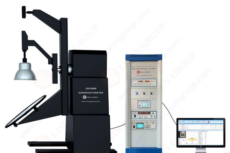
Contemporary industrial implementations of Type C goniophotometry are exemplified by the LM-79 Moving Detector Goniophotometer (Mirror Type C), Product No: LSG-6000, manufactured by LISUN. This system represents an advanced configuration specifically engineered to satisfy the stringent requirements of LM-79-19 Clause 7.3.1, CIE-121, and EN13032-1 clause 6.1.1.3 Type 4 specifications for precision photometric characterization.
The LSG-6000 employs a moving detector mirror architecture wherein the photodetector travels synchronously with a large plane mirror assembly, maintaining direct optical coupling to the stationary luminaire under test. This configuration ensures that the burning position—critical for thermal management in SSL products exhibiting significant heat dissipation—remains invariant throughout the C-plane rotation sequence (C-axis: ±180° or 0-360°) and vertical axis rotation (γ: ±180° or 0-360°).
Mechanical precision is achieved through the integration of high-precision rotary motors and absolute angle decode systems, delivering angular positioning accuracy of 0.05° with 0.001° resolution. This precision is essential for calculating narrow-beam luminaire metrics where small angular deviations produce significant intensity measurement errors. The optical path incorporates a constant-temperature photodetector (Class L per DIN5032-6/CIE Pub. No. 69) to eliminate thermal drift during extended measurement cycles.
The system accommodates diverse luminaire geometries through a modular design approach, with specific configurations optimized for dimensional and mass requirements:
Table 2: LSG-6000 series technical specifications for various luminaire testing requirements.
| Configuration | Maximum Luminaire Dimensions (Dia × Depth) | Weight Capacity | Minimum Darkroom Height | Power Supply Capacity |
| LSG-6000 (Standard) | Φ1600 mm × 600 mm | 50 kg | 4.1 m | 600V/10A AC/DC |
| LSG-6000S (Compact) | Φ1200 mm × 500 mm | 40 kg | 3.0 m | 600V/10A AC/DC |
| LSG-6000B (Extended) | Φ1800 mm × 800 mm | 60 kg | 4.7 m | 600V/10A AC/DC |
| LSG-6000L (Large Format) | Φ2000 mm × 900 mm | 80 kg | 5.2 m | 600V/10A AC/DC |
The LSG-6000 platform enables comprehensive photometric characterization beyond basic luminous intensity distribution. The system measures zonal luminous flux, luminaire luminous efficiency, luminance distribution (optional), utilization coefficients, and glare indices including UGR (Unified Glare Rating) and EEI (Energy Efficiency Index). Software implementation supports standard file format export including IES, LDT, and CIE formats, ensuring interoperability with illumination design software such as DIALux.
For applications requiring spectral characterization, the LSG-6000CCD configuration integrates a CCD spectroradiometer system (LPCE-2), creating a goniospectroradiometer capable of measuring spatial CCT distribution and color consistency across emission angles. This dual-system approach is particularly critical for horticultural lighting applications requiring PAR (Photosynthetically Active Radiation), PPF (Photosynthetic Photon Flux), and PPFD (Photosynthetic Photon Flux Density) spatial distribution analysis.
Installation precision is facilitated by a specialized collimation device incorporating cross-hair laser alignment, enabling sub-millimeter positioning of the luminaire’s photometric center at the intersection of the C and γ rotational axes. The control interface operates via USB connectivity with software compatibility across Windows 7/8/10/11 platforms, supporting automated measurement sequences that minimize operator intervention and ensure repeatable test light intensity protocols.
For ultraviolet lighting characterization, the system supports optional photodetector modules covering specific wavelength ranges:
These options extend the LSG-6000’s applicability beyond visible range photometry into medical, sterilization, and specialized industrial lighting sectors requiring radiometric rather than purely photometric evaluation.
Selecting appropriate instrumentation to test light intensity requires careful evaluation of measurement uncertainty budgets, sample throughput requirements, and long-term metrological maintenance. Laboratories must balance the capital investment in high-precision goniophotometer systems against the technical requirements of their specific testing portfolios.
For facilities conducting regulatory compliance testing, adherence to LM-79-19 and CIE-121 standards is non-negotiable, requiring Type C geometry with documented angular accuracy better than 0.1°. The measurement range must accommodate both high-intensity directional luminaires (requiring detectors with high dynamic range) and diffuse sources (requiring sensitive low-light detection capabilities). Thermal management considerations are particularly critical for SSL characterization, where junction temperature stabilization periods may extend measurement cycle durations significantly.
The integration of spectral measurement capabilities represents a significant value addition for modern photometric laboratories, enabling single-setup characterization of both intensity and color quality metrics. However, this integration increases system complexity and requires additional calibration procedures for spectral irradiance responsivity. Facilities should evaluate their client requirements regarding UGR calculations, glare assessments, and specific application testing (such as plant growth lighting) when configuring system capabilities.
Maintenance protocols must include regular angular calibration using autocollimators or polygon mirrors, photometric calibration using standard lamps with traceable luminous intensity values, and annual system verification against reference luminaires to detect long-term drift in detector responsivity or mechanical positioning accuracy.
The precise test light intensity methodology requires systematic adherence to international photometric standards, sophisticated instrumentation engineering, and rigorous laboratory environmental controls. As demonstrated through the analysis of Type C goniophotometer systems, achieving measurement uncertainties below 2% necessitates angular positioning accuracy of 0.05° or better, thermally stabilized Class L photodetectors, and comprehensive stray light suppression within purpose-designed darkroom facilities.
The technical evolution of moving detector mirror systems has established these platforms as the definitive methodology for solid-state lighting characterization, providing the geometric accuracy and measurement repeatability required for both regulatory compliance and advanced lighting research. Future developments in photometric instrumentation will likely emphasize enhanced automation, real-time spectral analysis integration, and improved software algorithms for glare assessment and energy efficiency calculations, further solidifying the role of precision goniophotometry in the lighting industry’s quality assurance infrastructure.
Tags:LSG-6000
LISUN’s indoor and outdoor LED test solutions meet IEC 60598-1, IEC 62722-2-1, CIE 121 standards, covering safety, photometry, and environmental tests for global compliance.

 中文简体
中文简体