
LM-79 Moving Detector Goniophotometer (Mirror Type C)
LSG-6000

High Precision Rotation Luminaire Goniophotometer
LSG-1890B

High Precision Rotation Luminaire Goniospectroradiometer
LSG-1890BCCD

Goniophotometer for Automotive and Signal Lamps
LSG-1950

Goniophotometer for Traffic Signal Lamps
LSG-1950S

Compact Goniophotometer
LSG-1200A

Near Field Moving Detector Goniophotometer
LSG-1900B
Select an organization
to browse standards
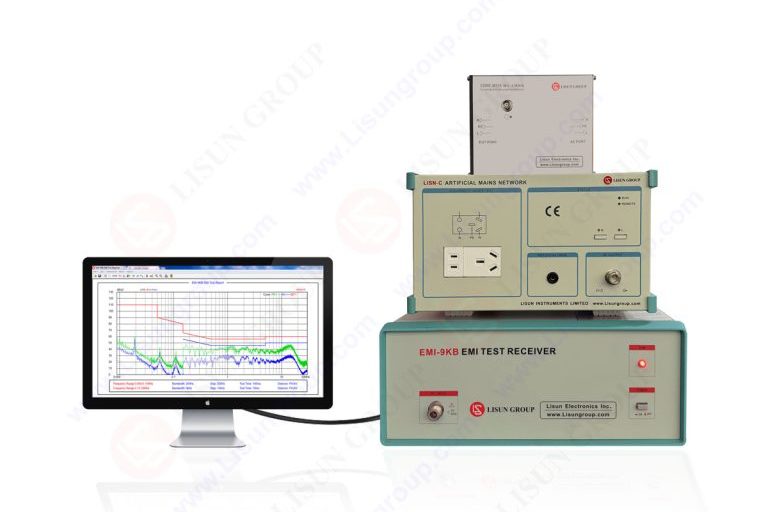
EMI-9KB is popularly utilized in compliance and pre compliance laboratories to obtain fine EMI testing, and a repeatability and stability of testing is of utmost significance. In radiated and conducted measurements of small perturbations across the electromagnetic environment can cause a shift of results by multiple decibels. These variations are not in any way related to the equipment being tested anyway but rather due to bad shielding or bad grounding architecture. Historical data on the interaction between shielding and grounding and the EMI-9KB measurement chain is subsequently fundamental to the realization of defensible and repeatable data in contemporary EMC-based labs.
Measurement instability is normally in the form of varying noise floors floating in or out of peak levels or varying quasi peak values in successive scans. These effects indicate uncontrollable coupling patterns letting external interference or internal ground loops affect the receiver. A proper shielding and grounding plan does not simply lessen noises. They create a predictable reference environment which allows the EMI-9KB to be able to work within their known limits of performance.
The initial measure of protection against undesired electromagnetic energy seeking access into the measurement system is known as shielding. In the case of the EMI-9KB shielding strategy should deal with radiated coupling into cables as well as conducted coupling between shared infrastructure. Sensitively shielded environment provides that the receiver is only responding to emission of equipment being tested and not the noise produced around the laboratory.
The strongest source of radiated immunity of the measurement arrangement is shielded rooms or screened enclosures. The integrity of panel continuity of doors gaskets and the treatment of penetrates is an essential factor in the efficacy of such enclosures. Such tiny holes or bonded joints may serve as slot antennas that allow outside signals through. In ensuring maintenance of long term stability of measurement, regular checking of shielding effectiveness is thus a component.
In the shielded space cable shielding also becomes a factor in importance. The coaxial cables between the EMI-9KB and LISN units antennas or transient limiters should have intact shields having low transfer impedance. Aging cables or connectors with plating that is worn out provide leakage paths that increases noise floor. Keeping routing cables near conductive reference planes and also avoiding huge loops would minimize magnetic coupling that otherwise can go unshielded.
Racks and benches also have internal shielding which helps them to stay stable. Racks of metal instruments attached to the reference ground plane are secondary shields and minimize cross coupling between instruments. Interference is further reduced when EMI-9KB is attached together with power supplies controllers or inside 2 partitioning of computers.

Shielding does not usually have the same importance as grounding when making measurements. The EMI-9KB bases its disturbance voltage and disturbance current measurement on a well defined reference ground to measure disturbance voltages and currents with great precision. Any uncertainty in ground potential causes uncertainty which is expressed in the form of variation in measurement.
EMIs preferring single-point grounded philosophy One-point grounded philosophy tends to be favored in EMI test layouts. A reference to a common ground plane should be provided to all of the major components such as the EMI-9KB LISN equipment under test and the auxiliary instruments. This would reduce the number of ground loops that would inject unwanted currents at the receiver input. The current plane, per se, should be a continuous low impedance conductive surface bonded to protective earth at a unique defined point.
The quality of bonding is a common cause of instability. Large copper straps, or braided unity ties, have lower inductance than thin wire, and remain useful throughout the range of frequencies of interest. The fastening points should be in clean state without paints or oxidation and should be mechanically fixed. It has to be checked periodically since connectivity on vibration and thermal cycling loosens with time.
Of particular attention is the EMI-9KB chassis-ground plane connection. Even though the instrument is safety grounded by the use of power cord another bonding strap to the reference plane tends to enhance the high frequency stability. This additional bond balances the possible differences, which arise between the power and ground line and limits the common mode noise as it gets into the receiver.
Most laboratories are not unstable in measurement but rather through use of auxiliary devices in the testing set up. Computers network switches are power and lighting systems produce broadband noise which is coupled into the EMI-9KB via the power and ground connections. Good shielding and grounding procedures should be carried out outside of the immediate test instruments.
The distribution of power is one of the factors to consider. Providing the EMI-9KB and sensitive accessories with a dedicated power source that is filtered suppresses the conducted noise. Further distortion of the building supply can be eliminated with isolation transformers and power line filters. It should be taken care of that these devices do not cause ground reference shifts which are incompatible with the single point grounding scheme.
Peripherals equipment must be considered in terms of noise additions. Where devices not needed in the test are present, they can be shut off or physically taken out of the shielded area. To contain emissions, vital equipment like control computers shielded enclosure and filtered feed throughs aids in limiting significant radiation. The grounding of these devices to a single common plane eliminates any possible action between the two devices that causes a noise current to flow through connecting cables.
Stability due to LISN placement and grounding also affects stability. The LISN should then be grounded and well bonded to the ground plane and installed as per standard layout requirements. Unattached or erratic placement will change impedance properties and influence conducted emission outcomes. Where installed properly the LISN is an operational defined impedance as well as a filter that will allow external noise to pass through it.
In addition to the theoretical concepts applied in practical layout decisions shape the success of shielding and grounding concepts. Cables and bonds of the equipment should be universally documented in physical arrangement. The importance of reproducibility is comparable to that of absolute performance since compliance testing tends to be time-intensive and performed regularly.
Magnetic coupling is reduced by separating high current circuits and sensitive measurement wires. Crossover of cables is necessary when they have to be separated and run parallel when running over short distances. The length of the cables must not be long since this will create improper antennas. Where slack is needed then it should be folded in a small design near the ground plane.
Auto-checkup is a crucial component of the stability of measurements. The equipment being tested scanned with background noise gives a background of the EMI-9KB environment. Periodical repetition of these scans shows that there is a gradual loss in shielding or grounding performance. The injection of known reference signals and a comparison of the measured levels with time also gives a confidence that the receiver and the surrounding environment are stable.
There is long term stability that is backed up. Documentation of grounding points bonding techniques types of cable used and routing enables future operators to recreate the system as it was. This is particularly necessary in quality-laboratories where staffs are bound to change.
As part of standardized test environments, manufacturers of EMC instrumentation create receivers, such as the EMI-9KB, to be used in a specific manner. Nevertheless, to reach the optimal stability, system level integration is involved as opposed to instrument specifications. The test system providers like LISUN have highlighted the shielding and grounding theory as application support since implementation of this theory may directly influence the credibility of the measurement.
Built-in systems based on combining the EMI-9KB and matched LISN units transient limiters and shielded accessories make grounding architecture simpler and variability less. By employing part designs which interconnect, the impedance mismatch and undesired coupling paths is reduced as much as possible. Such an approach towards systems is especially useful when a laboratory carries out both conducted and radiated EMI tests on the same equipment.
The receiver settings are not enough to achieve measurement stability when operating the EMI-9KB. It is an achievement of planned shielding and grounding measures which regulate the entry and the flow of electromagnetic energy within the test set up. Proper shielding eliminates external interference and proper grounding is used to provide a maintained reference potential to provide correct EMI testing. With structured grounding architecture and control of conducting noise paths, as well as, performance evaluation by check routine lab tests, it is entirely possible to achieve the achievement of the precision of the EMI-9KB and produce the results that would be stable and reliable over time.
Tags:EMI-9KB
LISUN’s Motor-Operated Tool | Power Tool Testing solutions strictly comply with a range of core international standards, providing full support for safety and electromagnetic compatibility (EMC)...

LISUN’s transformer test solutions meet IEC 61558-1, IEC 60076-1, IEC 62041 standards. Covering safety, performance, EMC tests, ensuring transformers comply with global requirements.

LISUN’s household and appliance switch testing solutions meet IEC 60669, IEC 61058, IEC 62271 standards. Covering electrical, mechanical & EMC tests for global compliance.

For the CFL design and manufactory, LISUN can supply a full quality control test solution, including photometric, colorimetric, electricity, flicker, IES candela distribution, surge test, electrical...

 中文简体
中文简体
