LM-79 Moving Detector Goniophotometer (Mirror Type C)
LSG-6000

High Precision Rotation Luminaire Goniophotometer
LSG-1890B

High Precision Rotation Luminaire Goniospectroradiometer
LSG-1890BCCD

Goniophotometer for Automotive and Signal Lamps
LSG-1950

Goniophotometer for Traffic Signal Lamps
LSG-1950S

Compact Goniophotometer
LSG-1200A

Near Field Moving Detector Goniophotometer
LSG-1900B
Select an organization
to browse standards
What does an Automatic Safety Test System do?
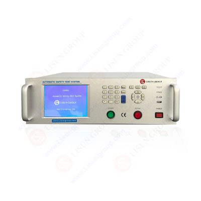
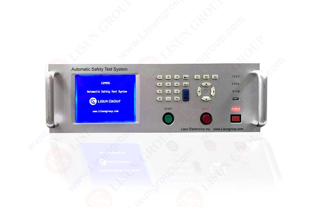
Withstand Voltage (AC/DC), Insulation Resistance (IR), Leakage Current (LLC), Ground Resistance (GR), and Power may all be tested using the Automatic Electrical Safety System. Withstand Voltage Test (AC/DC), Insulation Resistance Test (IR), Leakage Current Test (LLC), Grounding Resistance Test (GR), and Power Test were all included in the LS9955/LS9956 Automatic Safety Test System (electrical safety analyzer). In a production line or R&D lab, it is used to test the safety of motor tools, luminaires, and household applications.

LS9955_Automatic Safety Test System
Standards met by Automatic Safety Test Systems
According to GB4706.1, IEC/EN60335-1, UL60335, GB7000, IEC60598, GB4943, IEC60950, and GB9706.1, the LS9955/LS9956 Automatic Safety Test System was created.
Specifications
The device is remote controlled and has software control as well. Limit values for PASS/FAIL can be defined in it. All configuration settings and testing results are displayed in one large LCD menu. It has an alert sound and an indicator light, programmable test mode, 50 group settings, and eight test steps per group. It also has quick discharge. The LS9955 can do tests for Withstand Voltage (AC/DC), Insulation Resistance (IR), Leakage Current (LLC), Ground Resistance (GR), and Power. The LS9956 can perform tests for Withstand Voltage (AC/DC), Insulation Resistance (IR), Leakage Current (LLC), Ground Resistance (GR), and Power.
What kind of testing can be done?
Insulation resistance tests, leakage current tests, and grounding resistance tests can all be done using automatic safety test systems.

Insulation Resistance Testing
The most common test to determine the dependability of cables or windings in transformers, switchgear, motors, and electrical installations is the insulation resistance test, which is not the most recent test. A frequent test carried out on various cables and electrical lines is the IR measuring test. This test is widely used as a production test with minimum insulation resistance for each unit length that is frequently required by the customer.
What is it?
The test used to evaluate the overall resistance between any two sites that are separated by electrical insulation is known as the insulation resistance test. The megger test is another name for this procedure. Therefore, this test is performed to ascertain how well the insulation or dielectric works to limit the passage of electric current. Therefore, IR tests are highly useful for confirming the insulation quality of a product both during manufacture and during usage.
Why do you need to test for insulation resistance?
When an electric current is sent through a conducting wire to its destination, a loss in electric current occurs along the way for a variety of reasons. In order to determine whether there is any present leakage, we must conduct insulation testing because this leakage might be quite harmful. In order to avoid harm and damage, this testing is absolutely necessary.
In order to ensure the dependability of the electrical equipment, this test should be performed. By doing this test, we can very immediately determine the service life of the insulation and determine whether the electrical equipment is in excellent condition. When repairing new electrical equipment, insulation testing should be done as well. By testing electrical equipment, we can confirm that the insulation is functionally sound.
The idea behind insulation resistance testing
When the insulation in electrical devices, parts, and equipment used in industrial plants, buildings, and other settings deteriorates over time of use, hazards such as electric shock and short-circuits are caused. Portable insulation resistance testers and megohmmeters are designed to help prevent these hazards.
There is a chance of a ground fault or an electric shock when the insulation between charged and non-charged parts of electrical devices and equipment uses the kind of construction. A short-circuit is possible if the insulation between two or more charged potions deteriorates.
Leakage Current Test
A grounding technique is typically used in electrical systems to protect users from shock hazards in the event of an insulation problem. A grounding rod that connects the instrument to the earth is part of the grounding system. The voltage will be forced to ground if there is ever a catastrophic failure of insulation between a power line and conductive components. The electricity generated by this occurrence will flow, opening a circuit breaker or blowing a fuse to prevent a shock hazard.
It is obvious that if the earth or ground connection is impeded, whether accidentally or on purpose, a shock hazard exists. If leakage currents are present, the likelihood of a shock could be higher than initially thought. An individual coming into contact with an ungrounded system and ground at the same time could nevertheless receive an electric shock even in the absence of insulation failure due to leakage current intrusion.
When it comes to medical applications, where a patient could receive an electric shock, this is a serious worry. If the patient is frail or unconscious or if the electricity runs to internal organs, a shock may even be lethal. Non-grounded equipment has two layers of insulation to assure safety. Because it is unlikely that both coats of insulation will collapse simultaneously in this situation, security is guaranteed. However, the circumstances that cause leakage currents still exist and must be taken into account.
So how can leakage current be eliminated or its effects minimized? Discover the cause after measuring the leakage current. The goal of the test is to gauge how much current permeates a person when they come into contact with an electrical item.
What are the workings of such a test?
A meter made specifically for measuring leakage currents is used. The meter is connected in series with the earthing connection to measure the current flowing through the ground rod. To monitor the current flowing to the neutral side of the power line for data processing equipment, the ground connection is opened. The meter can also be linked to the ground and the power supply outputs. The neutral connections and ac line are switched, and power switches are turned on and off while the current is being watched. After the system has warmed up to its usual operating temperature, the test is conducted.
Determining and measuring the worst-case leakage current is the goal. The meter is replaced with a network made up of either a resistor or a cluster of resistors and capacitors for very small leakage currents. An AC voltmeter is then used to measure the voltage drop throughout the network. Attaching the meter between any touchable conductive portion and the earth allows you to determine if your equipment is double-insulated or unground. The current flowing from a copper foil with a particular dimension put on a nonconductive housing to ground is measured.
Benefits of Leakage Current Measurement
Benefits include the fact that when the test device is not in use, its polarity is not required to be reversed. There is also low stress due to high switching current. Leakage current may be a symptom that the insulation covering conductors is ineffective. With the use of a low current leakage current clamp, it is possible to identify the source of leakage current and interpret systematic results as required. This enables you to more impartially re-allocate loads throughout the system as needed.
Grounding Resistance Test
Ground resistance is the term used to describe the resistance that exists between a grounding electrode and the earth. In more technical terms, ground resistance is the sum of the resistances of the earth, the grounding conductor, and the resistances at their points of contact.
Characteristics
Because the earth functions like an electrolyte, it exhibits polarizing action, which prevents proper measurement by causing a DC current to produce electromotive force in the opposite direction. So, in order to measure ground resistance, a square wave or sine wave with a frequency of several hundreds of hertz to 1 kHz is typically used.
The resistance between a grounding electrode and the earth is known as ground resistance. Without putting the electrode into the ground, it cannot be measured. Earth has a relatively low resistivity, thus there is a voltage drop close to the electrode where the measurement’s current flows from. Therefore, you must go back about 10 meters in order to precisely measure the resistance value of each grounding electrode (the E electrode, S [P] electrode, and H [C] electrode).
Disturbances such ground potential and the impacts of the supplementary grounding electrodes can interfere with the measurement of ground resistance. The signal that the ground resistance tester measures is superimposed with ground potential due to leakage current from devices connected to the grounding electrode, which affects measured values. The measurement current will also drop if the auxiliary grounding electrodes have a high ground resistance, making the test more vulnerable to noise like ground potential.
Measuring Principle
An ammeter is used to gauge the amount of AC current I that flows after applying a voltage from an AC power source between the H (C) and E electrodes. Additionally, an AC voltmeter is used to measure the voltage V that develops when the current I runs between the S (P) and E electrodes.
The observed current I and voltage V are then used to compute the ground resistance RX of the E electrode. The voltage between the H (C) and E electrodes and the voltage between the H (C) and S (P) electrodes cannot be measured precisely.
FAQs
How many types of insulation resistance tests are there?
A megger or mega-ohm meter may carry out three different types of insulation resistance testing, such as the following.
Short-Time or Spot-Reading Test: By simply connecting a Megger device across the insulation that has to be tested, one can easily execute this kind of insulation resistance test. Following that, it is used for a brief amount of time, usually 60 seconds. It is crucial to keep in mind that the circumstances of humidity, temperature, and insulation affect the reading during the test.
Time-Resistance Method
Method of Time Resistance
This kind of testing methodology typically yields conclusive data devoid of prior test results. In contrast to contaminated insulation, this test primarily rely on a good insulation absorption effect. A tool like a Megger will take precise, straight measurements at regular intervals throughout this insulation test and record any variations. If the insulation is sound, this type of time resistance test must reveal a consistent rise in resistance over a predetermined length of time.
Dielectric Absorption Ratio
This ratio of two time-resistance readings is highly helpful for storing insulation-related data. A Megger gadget will make this test easy and provide the best results because, for example, a one-minute reading can be divided by a 30-second reading. This device can therefore run for one minute, but it also allows you to record measurements every 30 seconds and every minute.
Where can insulation resistance tests be used?
The following are some uses for insulation resistance tests.
• This test is carried out to prevent risks like short-circuits and electric shocks brought on by insulation degradation in electrical devices, equipment, and parts used in industrial plants and buildings over extended periods of usage.
• The entire resistance between any two places separated by electrical insulation is measured using the IR test.
In what case can a leakage test be failed?
The most frequent cause of equipment appearing to fail a leakage test is the adoption of an improper limit. The 5th edition of the IET Code of Practice lowered the threshold for the leakage test to 5mA for all Class I and Class II equipment. Based on earlier iterations of the IET Code of Practice, the majority of test equipment are pre-set to the older leakage limitations. To avoid unnecessarily failing equipment, manual interpretation of the test result may be necessary if the test instrument cannot be reprogrammed with the 5mA restriction. Leakage readings of 5 mA or less should be regarded as passing.
Lisun Instruments Limited was found by LISUN GROUP in 2003. LISUN quality system has been strictly certified by ISO9001:2015. As a CIE Membership, LISUN products are designed based on CIE, IEC and other international or national standards. All products passed CE certificate and authenticated by the third party lab.
Our main products are Goniophotometer, Integrating Sphere, Spectroradiometer, Surge Generator, ESD Simulator Guns, EMI Receiver, EMC Test Equipment, Electrical Safety Tester, Environmental Chamber, Temperature Chamber, Climate Chamber, Thermal Chamber, Salt Spray Test, Dust Test Chamber, Waterproof Test, RoHS Test (EDXRF), Glow Wire Test and Needle Flame Test.
Please feel free to contact us if you need any support.
Tech Dep: [email protected] , Cell/WhatsApp:+8615317907381
Sales Dep: [email protected] , Cell/WhatsApp:+8618117273997

LISUN’s household and appliance switch testing solutions meet IEC 60669, IEC 61058, IEC 62271 standards. Covering electrical, mechanical & EMC tests for global compliance.

For the CFL design and manufactory, LISUN can supply a full quality control test solution, including photometric, colorimetric, electricity, flicker, IES candela distribution, surge test, electrical...

LISUN’s LED driver test solutions cover lab testing, online testing, EMC/EMI tests, and safety checks, meeting IEC 60335, UL 60335 standards for reliable performance evaluation.

 中文简体
中文简体