LM-79 Moving Detector Goniophotometer (Mirror Type C)
LSG-6000

High Precision Rotation Luminaire Goniophotometer
LSG-1890B

High Precision Rotation Luminaire Goniospectroradiometer
LSG-1890BCCD

Goniophotometer for Automotive and Signal Lamps
LSG-1950

Goniophotometer for Traffic Signal Lamps
LSG-1950S

Compact Goniophotometer
LSG-1200A

Near Field Moving Detector Goniophotometer
LSG-1900B
Select an organization
to browse standards
One of the electromagnetic compatibility tests is a continuously performed radiofrequency (RF) immunity test. This is done by RF conducted immunity test system.
In the context of the EN standards for settings that are often household, commercial, or industrial, this property is commonly referred to as conducted electromagnetic susceptibility (EMS). In some industries, such as the automotive, aerospace, and space industries, as well as the railway and marine industries, several types of immunity testing may be necessary. Every sector uses its own set of immunity testing requirements.
Description
Contrary to radio frequency (RF) that is radiated into the environment, radio frequency (RF) that is conducted focuses on coupling and exposure via linked lines or cables. Both capacitive and inductive coupling systems can deliver noise transmissions onto related wires, which may make their way to electronic or electrical equipment.
The amounts of interference that are sent over these conducted cabling lines will have varying degrees of intensity depending on the field to which they are subjected. When there is a bigger electric or magnetic field, there will also be a greater degree of radio frequency (RF) noise that will move over the related cabling.
Conducted RF Immunity Testing
To conduct RF noise or interface, immunity testing tries to mimic the same environmental stress by using various injection and testing techniques. The following graphic explains the ideas behind the test that is typically carried out in accordance with IEC 61000-4-6 and uses the replacement technique in conjunction with a coupling decoupling network (CDN).
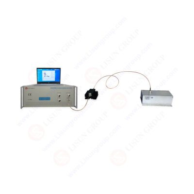
Test system
To conduct an accurate immunity test along power and data lines at speeds up to 1 GHz, RF conducted immunity test system is used. They can assess the DUT’s (the device under test) response to power fluctuations, which enables engineers to precisely analyze the device’s susceptibility when it is subjected to a dip in or spike in conducted energy.
When assessing the susceptibility of a device to potential decreases and surges in conducted energy, the testing standard IEC 61000-4-16 outlines all of the parameters it must meet. When conducting tests, the most frequent bandwidths vary from 10 kHz all the way up to 400 MHz.

RF conducted test system
Features:
Internal RF-Power Amplifier
Several amplifier modules are available. Over the stated frequency range, the maximum output power it may achieve is 75 W. Because it can access the amplifier input via the rear panel of the RFCI61000-6, it may utilize it not only with the internal generator but also with any external generator. Amplifiers with power outputs of 25 W and 75 W come as standard.
The RF power amplifier establishes the test level and frequency constraints in conjunction with the other equipment that relates to it.
When working with lower power levels, amplifiers are often included in the testing equipment. However, when working with greater power levels, amplifiers are typically external.
When an external amplifier is being used, a dual-directional coupler is required to carry out the standard forward and reverse power measurements that are carried out through the RF system. When conducting tests at higher levels, it is very necessary to make use of appropriate attenuation in order to assist in protecting the power meters or analyzer.
Internal RF-Voltmeter
The integrated three-channel RF-voltmeter, which may be accessible (for independent usage) through a BNC connection, is responsible for accurate measurements of RF signals with levels ranging from -40 dBm to +30 dBm. One channel is utilized to monitor the test level, while the other two use the built-in directional coupler to measure the forward and reverse power, respectively.
Internal RF-Signal Generator
Low levels of harmonics and spurious frequencies are guaranteed because to the fact that the internal generator creates the output signal without using any internal mixing components.
Amplitude Modulation
The low-frequency (LF) signal may be used to modulate the frequencies produced by the generator. The modulation frequency may be anywhere from 1 Hz up to 100 kHz, and the modulation level can be anywhere from 0% to 100%.
User-defined signals
The application software allows for connecting and monitoring external signals (such as EUT-fail or external instruments), for example.
Setup:
The RF conducted immunity test system RFCI61000-6 is a piece of test equipment operated by a personal computer. Any commercially available PC that is USB port compatible can use it. The control software, which is also included in the delivery, is used to make all the apparatus adjustments, such as the start frequency, the stop frequency, the step width, and the test voltage, amongst other things.
The software will automatically configure each of the three functional units—the RF signal generator, the RF power amplifier, and the RF voltmeter—based on the parameters pre-set for the test.
On the other hand, each component may be considered a standalone piece of measuring and testing apparatus and used as such. This implies that when you use the RFCI61000-6 as a testing system, you have three more “single units” at your disposal, each of which has its distinct inputs and outputs that can be connected to the RFCI via BNC cables.
Because the RFCI61000-6 is equipped with a computer-aided control system, any adjustments that may become required in the future, for instance, because of revision of standards, may be conducted without any hassles and the need to alter the hardware of the equipment.
Other types of equipment for conducted RF immunity
A capacitive connection to the cable being tested is the coupling technique that is the least complicated and easiest option. The signal of the disturbance is divided, using a coupling network, to each of the conductors in the cable. This is done to have the disruption appear in standard mode on all the conductors together.
To stop the signals being applied to the EUT from impacting other devices or being fed into the mains power supply, it is necessary to have a decoupling network and a coupling network.
The common-mode RF impedance at the EUT port is determined to be 150 ohms when a series resistance of 100 ohms is combined with the amplifier’s output impedance, which is 50 ohms. In most cases, the coupling and decoupling networks are merged into a single box to create what is referred to as a coupling/decoupling network (CDN).
Compared to other coupling techniques, the power needs are pretty modest; generally, 7W is sufficient to provide a 10V test level. In order to avoid the fluctuating output VSWR of the power amplifier from having an impact on the findings, an attenuator with a minimum gain of 6 dB is positioned between the amplifier and the network. A frequency range of 150 kHz to 80 MHz or higher is available for testing.
CDNs are available for a broad variety of applications, including screened cables, mains power leads, unscreened pairs, and non-balanced pairs; nevertheless, issues do exist for some kinds of unscreened cable, notably wideband balanced data pairs. The problem is comparable to that of testing emissions at telecom ports. The network (an Impedance Stabilizing Network in that context) must not interfere with transmitting the desired signal.
The EM Clamp
The EM-clamp is a helpful alternative to the CDN that it may use for RF injection. This device is made up of a tube that contains split ferrite rings of two different grades. It may clamp it over the cable it must check, and since it does not need intrusive procedures, it can use on any cable.
It can be utilized at frequencies as low as 150 kHz, in contrast to the CISPR absorbing clamp, which has a similar appearance but does not allow the inductive or capacitive connection.
The signal is brought in by a single-turn loop that runs the length of the clamp from one end to the other and is terminated in impedance at each of the clamp’s terminals. This creates a voltage, which provides the cable with capacitive coupling, and a current, which provides the cable with inductive coupling.
Because of the combination of graded ferrite and capacitive/inductive coupling, the clamp possesses significant directivity, particularly above 10 MHz. As a result, a significantly lower signal is applied to the AE end of the cable, and the typical mode impedance seen by the EUT is quite close to 150 ohms across a large portion of the spectrum of the test signal.
It may achieve a consistent impedance by correctly bonding the EM-clamp to the ground plane, the same as with the CDN. However, deviations brought on by cable configuration on the AE side of the test setup and those brought on by the AE itself are kept to a minimum.
To maintain a healthy output VSWR, the generator (power amplifier) output should be attenuated by a factor of 6 dB. Despite this additional attenuation, the coupling loss of the clamp is sufficiently low that it does not need much more power than a CDN to achieve equivalent levels.
LISUN has the best immunity test system for all kinds of testing.
The current probe
In addition to the EM-clamp and the CDN, there is also the possibility of using the current injection probe. It is not as successful as any of the other two options, but it is much simpler. The current probe is simply a clip-on current transformer that can be attached to any cable. It can measure current via any conductor.
Because it is insulated, it exclusively utilizes inductive coupling and does not include capacitive coupling of the test signal in any way. It has frequently been used in military and automotive testing (the “bulk current injection,” BCI test) for many years and has been included in IEC/EN 61000-4-6 as many test labs are acquainted with it. However, this has resulted in specific abnormalities in establishing the injected amount.
The two major drawbacks are the current probe’s lack of isolation from the peripheral device end of the wire and the lack of control over the cable’s common mode impedance. At lower frequencies, the cable’s resonances will determine how much current can flow through it, whereas at higher frequencies, the ratio of the typical mode impedances produced by the EUT, and the AE will determine how much current can flow.
Due to AE and cable impedances, the actual stress current supplied to the EUT is very varied and challenging to reproduce. Use of the present probe is discouraged unless necessary. Injection at the system level, where the AE and cable arrangement are known and fixed, is an ideal use case since CDNs and the EM-clamp have limited use due to physical constraints.
In addition, the current probe has a larger power need for given stress than any other approach because of the increased coupling loss.
Lisun Instruments Limited was found by LISUN GROUP in 2003. LISUN quality system has been strictly certified by ISO9001:2015. As a CIE Membership, LISUN products are designed based on CIE, IEC and other international or national standards. All products passed CE certificate and authenticated by the third party lab.
Our main products are Goniophotometer, Integrating Sphere, Spectroradiometer, Surge Generator, ESD Simulator Guns, EMI Receiver, EMC Test Equipment, Electrical Safety Tester, Environmental Chamber, Temperature Chamber, Climate Chamber, Thermal Chamber, Salt Spray Test, Dust Test Chamber, Waterproof Test, RoHS Test (EDXRF), Glow Wire Test and Needle Flame Test.
Please feel free to contact us if you need any support.
Tech Dep: Service@Lisungroup.com, Cell/WhatsApp:+8615317907381
Sales Dep: Sales@Lisungroup.com, Cell/WhatsApp:+8618117273997

LISUN’s Motor-Operated Tool | Power Tool Testing solutions strictly comply with a range of core international standards, providing full support for safety and electromagnetic compatibility (EMC)...

LISUN’s electric toy testing solutions cover IEC 62115, EN 71-1, ASTM F963 standards. Including electrical, mechanical, flammability tests to ensure toy safety compliance globally.

LISUN’s transformer test solutions meet IEC 61558-1, IEC 60076-1, IEC 62041 standards. Covering safety, performance, EMC tests, ensuring transformers comply with global requirements.

LISUN’s energy meter testing solutions align with IEC 62052-11, IEC 62053 series standards. Covering safety, electrical, environmental, and EMC tests, we help manufacturers meet global compliance...


 中文简体
中文简体