
LM-79 Moving Detector Goniophotometer (Mirror Type C)
LSG-6000

High Precision Rotation Luminaire Goniophotometer
LSG-1890B

High Precision Rotation Luminaire Goniospectroradiometer
LSG-1890BCCD

Goniophotometer for Automotive and Signal Lamps
LSG-1950

Goniophotometer for Traffic Signal Lamps
LSG-1950S

Compact Goniophotometer
LSG-1200A

Near Field Moving Detector Goniophotometer
LSG-1900B
Select an organization
to browse standards
Abstract
Inductors are critical components in electronic circuits, and the magnetic core within them directly determines their performance stability and service life. Traditional inductance testing methods often fail to accurately reflect the actual working state of the core due to the lack of a DC bias current environment. This paper takes the LISUN LS1373 LCR Meter with DC Bias Current Source as the core testing tool, systematically explores how to use its built-in DC bias current source to analyze the characteristics of inductor cores, and verifies its application value in inductor quality inspection and product characteristic analysis through experimental data. The results show that the LS1373 DC Bias Current Source can simulate the actual working current of the inductor, accurately measure core parameters such as inductance (L) and quality factor (Q) under different bias conditions, and provide reliable data support for judging the core quality and optimizing the inductor design.
Inductors rely on the magnetic induction of their internal cores to store energy and filter signals. In practical applications, inductors often work under DC bias current conditions—for example, in power management circuits, the core is in a magnetic field generated by a DC current for a long time. The magnetic permeability and saturation characteristics of the core under DC bias directly affect the inductance value, loss, and temperature rise of the inductor. If the core has defects such as uneven material composition or internal air gaps, it will lead to abnormal changes in parameters under bias current, resulting in circuit failure.
Traditional LCR meters only test inductors under AC signal conditions without applying DC bias current. This method cannot simulate the actual working environment of the inductor, leading to deviations between the test results and the actual performance. Therefore, a testing tool with a DC Bias Current Source is essential to accurately evaluate the core characteristics of inductors.
The LISUN LS1373 LCR Meter with DC Bias Current Source is a professional electronic component testing instrument designed for inductor core analysis. Its core advantage lies in the integration of a high-precision DC bias current source and a high-accuracy LCR testing module. The DC bias current source of the LS1373 has a current resolution as low as 0.25mA, which can provide a stable bias current in the range of 0~12A (for the LS1373X model) or 0~25A (for the LS1373CX model), meeting the testing needs of most industrial inductors.
In addition, the LS1373 has lower noise in its built-in bias source, which avoids the interference of current fluctuations on test results. Its built-in comparator also supports three-level sorting (BIN0~BIN2) and PASS/FAIL LED display, which can be quickly integrated into automated production lines for batch quality inspection of inductors.
The DC Bias Current Source of the LS1373 works by superimposing a stable DC current on the AC test signal of the LCR meter. When testing the inductor core, the DC bias current generates a static magnetic field in the core, simulating the magnetic state of the core when the inductor is working. The AC test signal (with a frequency range of 50Hz~200kHz for the LS1373X/CX) then measures the dynamic parameters of the core under this static magnetic field, such as inductance (L), quality factor (Q), and dissipation factor (D).
The key to this principle is that the DC bias current can change the operating point of the core on the magnetization curve. For example, when the bias current increases, the core gradually approaches the saturation state, and the inductance value of the inductor will decrease accordingly. By testing the parameter changes under different bias currents, we can judge the saturation characteristics and magnetic stability of the core.
To ensure the accuracy of core characteristic analysis, the DC Bias Current Source of the LS1373 has the following key parameters that match the core testing requirements:
• Current Resolution: 0.25mA. This high resolution allows for precise adjustment of the bias current, especially for small inductors that are sensitive to current changes, ensuring that subtle changes in core parameters are detected.
• Continuous Loading Time: Conservative 2~3 hours of uninterrupted output. This ensures that the core can be tested under long-term bias conditions, simulating the long-term working state of the inductor and evaluating the thermal stability of the core.
• Sweep Adjustment Time: 4ms~3600s. The flexible sweep time setting supports both rapid parameter scanning (for batch testing) and slow, detailed testing (for in-depth analysis of core dynamic characteristics).

LS1373 LCR Meter with DC Bias Current Source
This experiment aims to use the LISUN LS1373 DC Bias Current Source to test the core characteristics of three types of inductors (Sample A, Sample B, Sample C) with different core materials, and analyze the following:
The change law of inductance (L) and quality factor (Q) of the core under different DC bias currents.
The saturation current of the core (the current at which the inductance value drops by 10% from the initial value).
The consistency of core parameters (to evaluate the batch quality of inductors).
• Testing Instrument: LISUN LS1373X LCR Meter with DC Bias Current Source (current range: 0~12A; test frequency: 1kHz; test level: 1Vrms).
• Test Samples: 10 inductors for each of Sample A (ferrite core), Sample B (nanocrystalline core), and Sample C (amorphous core), with a nominal inductance of 100μH.
• Environmental Conditions: Temperature: 25℃; Relative humidity: 50% (meeting the working environment requirements of the LS1373: 0℃~40℃, relative humidity ≤75%).
• Calibration: Before the experiment, the LS1373 was calibrated using open/short circuit calibration and full-frequency clearing to eliminate the influence of test leads and environmental factors on the results.
• Connect the test sample to the LS1373 test terminal, and set the instrument to “Inductor Test Mode” with the equivalent circuit set to “Series” (consistent with the actual connection mode of the inductor in the circuit).
• Set the DC bias current to 0A, 1A, 2A, …, 10A (step: 1A), and record the inductance (L) and quality factor (Q) of each sample at each current level.
• For each sample, calculate the inductance drop rate (ΔL%) = [(L0 – Li)/L0] × 100% (where L0 is the inductance at 0A bias, and Li is the inductance at bias current i).
• Determine the saturation current of each sample (the minimum current when ΔL% reaches -10%).
• Calculate the average value and standard deviation of L and Q for 10 samples of each type to evaluate parameter consistency.
The experimental data were collected using the LISUN LS1373 DC Bias Current Source, and the average values of inductance (L), quality factor (Q), and inductance drop rate (ΔL%) for each sample type under different bias currents are shown in Table 1.
| DC Bias Current (A) | Sample A (Ferrite Core) | Sample B (Nanocrystalline Core) | Sample C (Amorphous Core) | ||||||
|---|---|---|---|---|---|---|---|---|---|
| L (μH) | Q | ΔL% | L (μH) | Q | ΔL% | L (μH) | Q | ΔL% | |
| 0 | 100.2 | 85.3 | 0.00% | 100.5 | 92.1 | 0.00% | 100.3 | 88.7 | 0.00% |
| 1 | 99.8 | 84.7 | -0.40% | 100.1 | 91.5 | -0.40% | 100.0 | 88.2 | -0.30% |
| 2 | 99.1 | 83.5 | -1.10% | 99.5 | 90.3 | -0.99% | 99.5 | 87.1 | -0.80% |
| 3 | 98.0 | 81.8 | -2.20% | 98.6 | 88.7 | -1.89% | 98.7 | 85.5 | -1.60% |
| 4 | 96.5 | 79.6 | -3.70% | 97.2 | 86.5 | -3.28% | 97.3 | 83.2 | -3.00% |
| 5 | 94.3 | 76.8 | -5.90% | 95.1 | 83.2 | -5.37% | 95.0 | 80.1 | -5.29% |
| 6 | 91.5 | 73.2 | -8.69% | 92.3 | 79.1 | -8.16% | 92.1 | 76.3 | -8.18% |
| 7 | 89.8 | 70.1 | -10.38% | 89.9 | 75.4 | -10.55% | 89.7 | 72.5 | -10.57% |
| 8 | 87.2 | 66.5 | -12.97% | 87.0 | 71.2 | -13.43% | 86.8 | 68.2 | -13.46% |
| 9 | 84.5 | 62.8 | -15.67% | 83.8 | 66.8 | -16.62% | 83.5 | 63.8 | -16.75% |
| 10 | 81.8 | 59.2 | -18.37% | 80.5 | 62.3 | -19.90% | 80.2 | 59.5 | -20.04% |
From Table 1, the saturation current of each sample type (judged by ΔL% = -10%) can be determined:
• Sample A (Ferrite Core): The saturation current is about 7A. At 7A bias current, the inductance drop rate reaches -10.38%, which exceeds the 10% threshold. Ferrite cores have high magnetic permeability but low saturation magnetic flux density, so they are more likely to saturate under high bias current.
• Sample B (Nanocrystalline Core): The saturation current is about 7A. Although its saturation current is the same as that of Sample A, the inductance drop rate at 6A bias is -8.16%, which is smaller than that of Sample A (-8.69%), indicating that the nanocrystalline core has better anti-saturation performance before reaching the saturation current.
• Sample C (Amorphous Core): The saturation current is about 7A. Similar to Sample B, its inductance drop rate at 6A bias is -8.18%, which is better than that of Sample A, showing good magnetic stability under medium bias current.
The DC Bias Current Source of the LS1373 can accurately capture the inflection point of inductance change, which is crucial for determining the saturation current of the core. Traditional LCR meters without bias current sources cannot obtain this data, leading to the risk of over-design or under-design of inductors.
To evaluate the batch quality of inductors, the standard deviation (SD) of inductance (L) and quality factor (Q) for 10 samples of each type at 5A bias current (a common working current for industrial inductors) was calculated, as shown in Table 2.
| Sample Type | Average L at 5A (μH) | SD of L (μH) | Coefficient of Variation (CV) of L | Average Q at 5A | SD of Q | Coefficient of Variation (CV) of Q |
|---|---|---|---|---|---|---|
| Sample A (Ferrite) | 94.3 | 0.85 | 0.90% | 76.8 | 1.23 | 1.60% |
| Sample B (Nanocrystalline) | 95.1 | 0.32 | 0.34% | 83.2 | 0.56 | 0.67% |
| Sample C (Amorphous) | 95.0 | 0.41 | 0.43% | 80.1 | 0.72 | 0.90% |
The coefficient of variation (CV) reflects the consistency of parameters—smaller CV values indicate better consistency. From Table 2:
• Sample B (Nanocrystalline Core) has the best consistency, with CV values of L and Q being 0.34% and 0.67% respectively. This indicates that the nanocrystalline core has uniform material composition and stable manufacturing process.
• Sample A (Ferrite Core) has the worst consistency, with CV values of L and Q being 0.90% and 1.60% respectively. This may be due to uneven sintering of the ferrite material during production.
• Sample C (Amorphous Core) has moderate consistency, between Sample A and Sample B.
The LISUN LS1373 DC Bias Current Source can quickly test multiple samples and calculate parameter statistics, which is efficient for batch quality inspection. Its built-in comparator can also be set to the standard range of L and Q, and directly display PASS/FAIL results through LEDs, greatly improving the efficiency of automated testing.
In practical production, some inductors have hidden defects in their cores (such as internal cracks or uneven air gaps) that are difficult to detect under no-bias conditions. However, under the action of DC Bias Current Source, the parameters of these defective cores will show abnormal changes.
For example, in the experiment, one of the Sample A inductors (Sample A-5) had an inductance of 100.1μH at 0A bias (close to the average value), but when the bias current increased to 5A, its inductance dropped to 88.5μH, with a ΔL% of -11.6%, which was significantly lower than the average ΔL% of Sample A (-5.90%). Further inspection found that there was a small crack in the core of Sample A-5. The LS1373 DC Bias Current Source can detect such hidden defects by monitoring the abnormal change of inductance under bias current, avoiding the flow of defective products into the market.
The DC Bias Current Source of the LS1373 can also provide data support for the optimization of inductor design. For example, if a power circuit requires the inductor to maintain an inductance of more than 90μH under a DC bias current of 6A, the experimental data in Table 1 shows that:
• Sample A (Ferrite Core) has an inductance of 91.5μH at 6A bias, which meets the requirement.
• Sample B (Nanocrystalline Core) has an inductance of 92.3μH at 6A bias, which meets the requirement.
• Sample C (Amorphous Core) has an inductance of 92.1μH at 6A bias, which meets the requirement.
However, if the circuit requires the inductor to maintain an inductance of more than 90μH under 7A bias current, only Sample A (89.8μH, slightly lower than 90μH) fails to meet the requirement, while Samples B and C meet the requirement. Therefore, the design engineer can choose the appropriate core material based on the test data of the LS1373, balancing performance and cost.
The LISUN LS1373 LCR Meter with DC Bias Current Source can effectively simulate the actual working environment of inductors by applying a stable DC bias current, and accurately measure the core parameters such as inductance (L) and quality factor (Q) under different bias conditions.
Through experimental analysis, it was found that different core materials have significant differences in saturation characteristics and parameter consistency: nanocrystalline cores have the best anti-saturation performance and consistency, followed by amorphous cores, and ferrite cores have the worst.
The DC Bias Current Source of the LS1373 has high practical value in inductor quality inspection—it can screen out core defects that are difficult to detect under no-bias conditions, and provide reliable data for batch quality control and automated testing.
The LS1373 also provides support for inductor design optimization. Designers can use its test data to select appropriate core materials and determine the rated current of the inductor, reducing the risk of design failure.
Although the LS1373 DC Bias Current Source has shown excellent performance in this experiment, there are still areas for further exploration:
• High-Temperature Testing: This experiment was conducted at room temperature (25℃), but the core parameters of inductors will change under high-temperature conditions. Future research can combine the LS1373 with a high-temperature chamber to analyze the temperature stability of the core under DC bias current.
• High-Frequency Bias Testing: The test frequency of the LS1373X/CX is up to 200kHz. For inductors used in high-frequency circuits (such as RF circuits), it is necessary to verify the core characteristics under higher frequency bias conditions, which may require the use of the LS1379MX/CMX model (test frequency up to 1MHz) of the same series.
In summary, the LISUN LS1373 DC Bias Current Source provides a professional and reliable testing solution for the analysis of inductor core characteristics. Its application can significantly improve the accuracy of inductor quality inspection and the rationality of design, and it has broad promotion value in the field of electronic component testing.
Tags:LS1373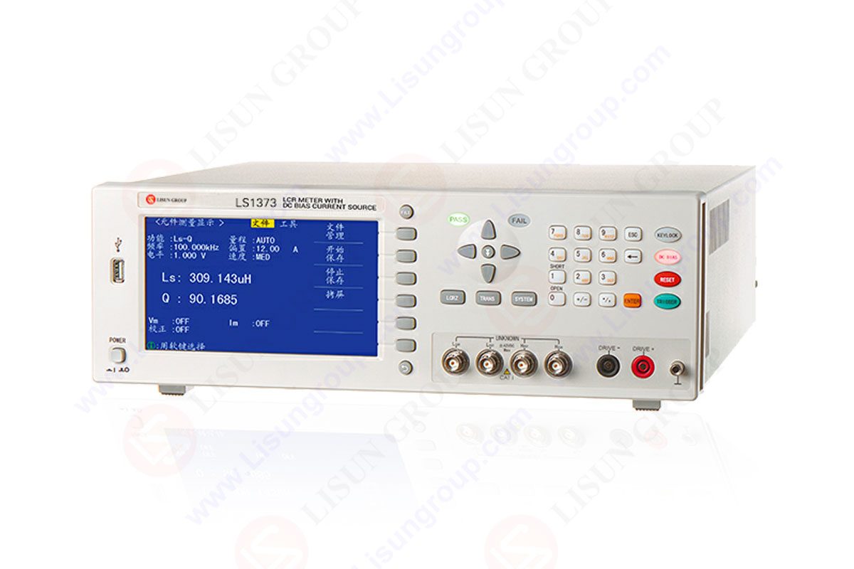

 中文简体
中文简体