
LM-79 Moving Detector Goniophotometer (Mirror Type C)
LSG-6000

High Precision Rotation Luminaire Goniophotometer
LSG-1890B

High Precision Rotation Luminaire Goniospectroradiometer
LSG-1890BCCD

Goniophotometer for Automotive and Signal Lamps
LSG-1950

Goniophotometer for Traffic Signal Lamps
LSG-1950S

Compact Goniophotometer
LSG-1200A

Near Field Moving Detector Goniophotometer
LSG-1900B
Select an organization
to browse standards
Abstract
With the rapid development of electronic and electrical systems, especially in the aerospace and military fields, the demand for reliable Electromagnetic Compatibility (EMC) testing equipment has become increasingly urgent. Voltage spike, as a typical electromagnetic interference (EMI) signal, can easily cause malfunctions or even permanent damage to sensitive electronic devices. The 600V Voltage Spike Generator, represented by the LISUN DO160-S17 model, is a core device designed to simulate such voltage spike interference and verify the EMC performance of Equipment Under Test (EUT). This paper takes the LISUN DO160-S17 600V Voltage Spike Generator as the research object, systematically introduces its working principle, detailed technical parameters, structural design characteristics, and practical application scenarios in compliance with international standards such as RTCA DO-160 Section 17 and MIL3-DO-160-S17. Through the analysis of its performance indicators and test process, this paper demonstrates the important role of the 600V Voltage Spike Generator in ensuring the stability and safety of electronic systems in harsh electromagnetic environments.
In electronic and electrical systems, voltage spike refers to a short-duration, high-amplitude transient voltage signal that usually lasts for microseconds (μs) and has a peak voltage much higher than the normal operating voltage of the system. Voltage spikes can be generated by a variety of sources, including switching operations of power electronic devices (such as inverters and rectifiers), lightning strikes, fault short circuits in power grids, and electromagnetic induction in adjacent circuits. For example, in aerospace systems, the switching of on-board power supplies or the operation of high-power actuators can generate voltage spikes on the power supply lines, which may interfere with the normal operation of avionics equipment such as navigation systems and communication modules. In military equipment, voltage spikes caused by battlefield electromagnetic environments can directly affect the combat effectiveness and reliability of weapons and equipment.
To ensure that electronic equipment can withstand the impact of voltage spike interference during actual operation, it is necessary to conduct targeted EMC testing during the product development and certification stages. The 600V Voltage Spike Generator is a specialized testing device that can generate standard voltage spike signals with a peak voltage ranging up to 600V, which covers the voltage spike interference levels required by most aerospace, military, and industrial standards. By applying the voltage spike signals generated by the 600V Voltage Spike Generator to the EUT (such as ungrounded input power supply lines), testers can evaluate the EUT’s ability to resist voltage spike interference, identify potential design flaws in advance, and optimize the EMC performance of the product.
The LISUN DO160-S17 600V Voltage Spike Generator, developed by LISUN GROUP (https://www.lisungroup.com/products/emi-and-emc-test-system/voltage-spike-generator.html), is a high-performance EMC testing equipment that fully complies with the requirements of RTCA DO-160 Section 17 and MIL3-DO-160-S17. This generator is designed for testing the voltage spike resistance of ungrounded input power supply lines of electronic equipment, with a pulse repetition frequency of 2Hz and a continuously adjustable pulse peak voltage from 100V to 600V. It adopts an Android operating platform, which provides abundant functions, convenient operation, easy software upgrading, and intelligent control, making it widely used in EMC testing of aerospace, military, and industrial electronic products.
The core function of the 600V Voltage Spike Generator is to generate a transient voltage spike signal that meets the standard requirements. Its working principle is mainly based on the energy storage and release of capacitors, combined with high-speed switching devices to control the duration and rise time of the spike. The specific process can be divided into three stages: energy storage, pulse formation, and signal coupling.
• Energy Storage Stage: The generator first uses a high-voltage DC power supply to charge a high-performance energy storage capacitor. The voltage of the DC power supply can be adjusted according to the required peak voltage of the voltage spike (ranging from 100V to 600V for the LISUN DO160-S17). During this stage, the switching device is in the off state, and the capacitor stores electrical energy stably.
• Pulse Formation Stage: When a trigger signal is received (the LISUN DO160-S17 adopts an automatic trigger mode), the high-speed switching device (such as a thyristor or IGBT) is rapidly turned on. The energy stored in the capacitor is quickly released through the load (including the internal impedance of the generator and the EUT), forming a transient voltage spike. The rise time of the spike is determined by the switching speed of the switching device and the parasitic inductance and capacitance in the circuit. For the LISUN DO160-S17, the rise time is controlled to be ≤2μs, which meets the requirements of RTCA DO-160 Section 17. The pulse duration (>10μs for the LISUN DO160-S17) is determined by the capacitance of the energy storage capacitor and the equivalent resistance of the discharge circuit, which can be adjusted by selecting different capacitor parameters.
• Signal Coupling Stage: The generated voltage spike signal needs to be effectively coupled to the power supply line of the EUT to simulate the actual interference scenario. The LISUN DO160-S17 is equipped with a built-in Coupling Decoupling Network (CDN) – an AC440V/16A single-phase CDN. The CDN has two main functions: on the one hand, it couples the voltage spike signal generated by the generator to the EUT’s power supply line; on the other hand, it decouples the EUT from the power grid, preventing the voltage spike signal from propagating back to the power grid and interfering with other equipment, and also preventing the grid voltage from affecting the test results.
The LISUN DO160-S17 600V Voltage Spike Generator consists of several key circuit modules, each of which plays an important role in ensuring the performance of the generator:
• High-Voltage DC Power Supply Module: This module provides a continuously adjustable DC voltage from 100V to 600V, which is used to charge the energy storage capacitor. It adopts a high-precision voltage regulation circuit to ensure that the output voltage is stable and accurate, thus ensuring the consistency of the peak voltage of the generated voltage spike.
• Energy Storage and Discharge Module: This module includes high-performance energy storage capacitors, high-speed switching devices, and current-limiting resistors. The energy storage capacitor is selected for its high voltage resistance, low parasitic inductance, and good stability. The high-speed switching device ensures that the capacitor can discharge quickly, generating a voltage spike with a fast rise time. The current-limiting resistor is used to protect the switching device and the EUT, preventing excessive current from causing damage during discharge.
• Trigger Control Module: The trigger control module is responsible for generating trigger signals to control the on-off of the switching device. The LISUN DO160-S17 adopts an automatic trigger mode, which can generate trigger signals at a set pulse frequency (max 2Hz). The trigger timing is precisely controlled to ensure that the voltage spike signals are generated at regular intervals, which is convenient for testers to observe the response of the EUT.
• Coupling Decoupling Network (CDN) Module: The built-in AC440V/16A single-phase CDN is an important part of the generator. It is designed in accordance with international standards to ensure that the coupling efficiency of the voltage spike signal meets the test requirements. At the same time, the CDN has a high impedance to the voltage spike signal in the reverse direction (towards the power grid), which effectively isolates the EUT from the power grid.
• Control and Display Module: The generator adopts an Android platform, which is equipped with a touch screen display and an intelligent control system. Testers can set test parameters (such as peak voltage, pulse frequency) through the touch screen, and the system can real-time display the test status and parameters. The software of the module supports online upgrading, which is convenient for updating the system function and adapting to new test standards.
The performance of the 600V Voltage Spike Generator is directly reflected in its technical parameters. The following table lists the detailed technical parameters of the LISUN DO160-S17 600V Voltage Spike Generator, which are crucial for evaluating its applicability in EMC testing:
| Technical Parameter | Specification of LISUN DO160-S17 600V Voltage Spike Generator |
| Product Model | DO160-S17 |
| Test Voltage Range | 100V – 600V (continuously adjustable) |
| Rise Time | ≤2μs |
| Pulse Duration | >10μs |
| Output Impedance | 50Ω ± 10% |
| Output Polarity | Positive and negative |
| Trigger Mode | Automatic |
| Pulse Frequency | Max 2Hz |
| Built-in CDN | AC440V/16A single-phase CDN |
| Operating Platform | Android |
| Compliance Standards | RTCA DO-160 Section 17, MIL3-DO-160-S17 |
The LISUN DO160-S17 has a test voltage range of 100V – 600V, which is continuously adjustable. This range covers the voltage spike levels required by most aerospace and military standards. For example, RTCA DO-160 Section 17 (which specifies the EMC requirements for avionics equipment) requires that the voltage spike test for ungrounded power supply lines should cover different voltage levels according to the type of EUT. The continuous adjustability of the 600V voltage range allows testers to gradually increase the voltage spike amplitude during the test, accurately find the threshold voltage at which the EUT begins to malfunction, and thus evaluate the EUT’s voltage spike resistance more comprehensively.
The rise time (≤2μs) and pulse duration (>10μs) of the voltage spike are two key parameters that affect the test accuracy. A fast rise time (≤2μs) can simulate the suddenness of actual voltage spike interference, which is crucial for testing the response speed of the EUT’s protection circuit. If the rise time is too slow, the test results may be optimistic, and the EUT may not withstand the actual fast-rise voltage spike. The pulse duration (>10μs) ensures that the voltage spike has enough time to affect the EUT’s internal circuits. For example, some sensitive electronic components (such as integrated circuits) may not be affected by a very short-duration spike, but a spike with a duration of more than 10μs can penetrate the protection circuit and cause data errors or component damage.
The output impedance of 50Ω ± 10% is consistent with the characteristic impedance of most test cables and EUT input ports, which can reduce signal reflection at the interface and ensure that the voltage spike signal is transmitted to the EUT without distortion. The positive and negative output polarity allows the generator to simulate both positive and negative voltage spikes, which is in line with the actual situation where voltage spikes can be either positive (higher than the normal voltage) or negative (lower than the normal voltage, such as voltage dips). For example, in a DC power supply system, a sudden disconnection of the load may cause a positive voltage spike, while a sudden increase in the load may cause a negative voltage spike. The LISUN DO160-S17’s ability to generate both polarities ensures that the test is more comprehensive.
The maximum pulse frequency of 2Hz means that the generator can generate up to 2 voltage spike signals per second. This frequency is sufficient for most EMC tests, as testers need to observe the EUT’s response (such as whether the display is normal, whether the data is lost) after each voltage spike is applied. The automatic trigger mode reduces the manual operation intensity of testers, especially in long-term stability tests. Testers only need to set the test parameters, and the generator can automatically generate voltage spike signals at the set frequency, which improves the test efficiency and reduces the error caused by manual trigger.
The built-in AC440V/16A single-phase CDN is a significant advantage of the LISUN DO160-S17. In traditional voltage spike tests, testers need to connect an external CDN, which not only increases the complexity of the test system but also may introduce additional signal distortion due to the mismatch between the external CDN and the generator. The built-in CDN of the LISUN DO160-S17 is specially designed to match the generator’s output characteristics, ensuring that the voltage spike signal is coupled to the EUT’s power supply line with high efficiency and low distortion. The AC440V/16A specification means that the CDN can handle a maximum AC voltage of 440V and a maximum current of 16A, which is suitable for most small and medium-sized electronic equipment (such as avionics sensors, industrial controllers) with ungrounded input power supply lines.

DO160-S17_Voltage Spike Generator
The LISUN DO160-S17 600V Voltage Spike Generator is mainly used in EMC testing of electronic equipment in the following fields:
• Aerospace Field: Avionics equipment (such as flight control systems, navigation receivers, communication transceivers) needs to comply with RTCA DO-160 Section 17. The LISUN DO160-S17 can simulate the voltage spike interference generated by on-board power supplies, actuators, and other devices, and test the EMC performance of avionics equipment. For example, during the certification test of a civil aircraft’s navigation system, the generator is used to apply 600V voltage spikes to the system’s ungrounded power supply line, and testers check whether the navigation system can still accurately receive and process satellite signals without any malfunctions.
• Military Field: Military electronic equipment (such as radar systems, missile guidance systems, communication equipment) needs to meet the requirements of MIL3-DO-160-S17. The harsh battlefield electromagnetic environment requires military equipment to have higher voltage spike resistance. The LISUN DO160-S17 can generate voltage spike signals that meet military standards, helping to verify the reliability of military equipment in the presence of voltage spike interference. For example, in the test of a military communication radio, the generator is used to apply positive and negative voltage spikes (up to 600V) to the radio’s power supply line, and testers evaluate whether the radio can maintain normal communication quality.
• Industrial Field: Industrial electronic equipment (such as PLC controllers, frequency converters, sensors) is often used in harsh industrial environments, where voltage spikes generated by power grid switching or large-scale motor operations are common. Although industrial standards (such as IEC 61000-4-5) have lower voltage spike requirements than aerospace and military standards, the LISUN DO160-S17’s 600V voltage range can also be used for high-level industrial EMC tests, especially for equipment used in critical industrial processes (such as power plants, chemical plants) that require high reliability.
Taking the voltage spike test of an avionics sensor (EUT) with an ungrounded input power supply line as an example, the typical test process using the LISUN DO160-S17 600V Voltage Spike Generator is as follows:
Test Preparation:
Connect the LISUN DO160-S17 600V Voltage Spike Generator to the power grid (ensuring that the input voltage is consistent with the generator’s requirements).
• Connect the EUT to the built-in CDN of the generator: the input power supply line of the EUT is connected to the output terminal of the CDN, and the CDN’s input terminal is connected to the power grid. This ensures that the voltage spike signal generated by the generator is coupled to the EUT’s power supply line through the CDN, and the EUT is decoupled from the power grid.
• Power on the generator and the EUT, and preheat them for a certain period of time (usually 10-15 minutes) to ensure that the equipment is in a stable working state.
• Set the test parameters on the generator’s Android touch screen: select the output polarity (positive first, then negative), set the initial peak voltage (such as 100V), set the pulse frequency (2Hz), and select the automatic trigger mode.
Test Execution:
• Start the generator’s trigger function. The generator automatically generates voltage spike signals with a peak voltage of 100V, a rise time of ≤2μs, and a pulse duration of >10μs at a frequency of 2Hz, and couples them to the EUT’s power supply line through the CDN.
• During the test, observe the EUT’s working status in real time: check whether the EUT’s indicator lights are normal, whether the output data is accurate (such as the sensor’s measurement value), and whether there are any abnormal phenomena (such as crash, restart, or data loss).
• Gradually increase the peak voltage of the voltage spike (each time increasing by 50V until the EUT shows abnormal behavior. For example, if the sensor’s output data suddenly becomes inaccurate or the sensor stops working when the peak voltage reaches 400V, record this voltage value as the EUT’s voltage spike failure threshold.
After testing with positive voltage spikes, change the output polarity of the generator to negative, and repeat the above steps to test the EUT’s resistance to negative voltage spikes.
Test Data Recording and Analysis:
• During the test, record the test conditions (such as peak voltage, pulse frequency, polarity), the EUT’s response (including normal operation, abnormal phenomena, and failure voltage threshold), and the time of each event.
• After the test is completed, analyze the test data. For example, if the EUT can withstand voltage spikes of 300V or less without any abnormal behavior, but starts to show malfunctions at 350V, it indicates that the EUT’s voltage spike resistance level is between 300V and 350V. Compare the test results with the EUT’s design requirements and relevant standards (such as RTCA DO-160 Section 17). If the EUT can withstand voltage spikes up to the required peak voltage specified in the standard without failure, it means that the EUT meets the EMC requirements in terms of voltage spike resistance; otherwise, the EUT needs to be redesigned or additional protection measures need to be added.
Compared with other voltage spike generators in the market, the LISUN DO160-S17 600V Voltage Spike Generator has the following advantages:
• Compliance with Aerospace and Military Standards: Many voltage spike generators only meet general industrial EMC standards, while the LISUN DO160-S17 fully complies with RTCA DO-160 Section 17 and MIL3-DO-160-S17, which are specifically for aerospace and military applications. This makes it more suitable for testing high-reliability electronic equipment in these fields. For example, some industrial-grade voltage spike generators may not be able to generate voltage spike signals with the precise rise time and pulse duration required by aerospace standards.
• Android Operating Platform and Intelligent Control: Some traditional voltage spike generators use simple button operation or basic digital control interfaces, which are not as user-friendly as the Android platform of the LISUN DO160-S17. The Android platform allows for easy parameter setting, real-time monitoring of test status, and software upgrading, improving test efficiency and flexibility. For instance, with the Android touch screen, testers can quickly switch between different test modes and view historical test data, while traditional generators may require complex operations to achieve the same functions.
• Built-in CDN: While some voltage spike generators require an external CDN to be connected, the built-in AC440V/16A single-phase CDN of the LISUN DO160-S17 simplifies the test system connection and ensures better signal coupling performance. External CDNs may introduce additional signal attenuation or interference due to improper connection or impedance mismatch, which is less likely to occur with the built-in CDN of the LISUN DO160-S17.
The 600V Voltage Spike Generator, especially the LISUN DO160-S17 model, plays a crucial role in EMC testing. By accurately simulating voltage spike interference with a peak voltage of up to 600V, it can effectively evaluate the voltage spike resistance of electronic equipment. Its working principle based on capacitor energy storage and high-speed switching device control ensures the generation of high-quality voltage spike signals. The rich technical parameters, such as adjustable voltage range, fast rise time, and appropriate pulse duration, make it suitable for a wide range of applications in aerospace, military, and industrial fields.
With the continuous miniaturization and high-integration of electronic devices, as well as the increasing complexity of electromagnetic environments, the requirements for voltage spike generators will become more stringent in the future. In terms of technology development, future voltage spike generators may have the following trends:
• Higher Voltage and Precision: To meet the needs of more extreme electromagnetic interference scenarios, such as high-voltage power systems or next-generation aerospace equipment, voltage spike generators may be required to generate higher peak voltage signals (even exceeding 600V) with higher precision in voltage regulation, rise time, and pulse duration control.
• Multi-functional Integration: Future generators may integrate more functions, such as the ability to generate combined interference signals (including voltage spikes and other types of electromagnetic interference, such as electromagnetic pulses or high-frequency harmonics) to simulate more complex real-world electromagnetic environments. At the same time, they may also be integrated with data acquisition and analysis systems, which can automatically analyze the EUT’s response data and provide more comprehensive EMC test reports.
• Wireless and Portable Design: With the development of wireless communication technology and the demand for on-site testing, voltage spike generators may adopt wireless control and portable design. Testers can control the generator through wireless devices (such as tablets or smartphones) at a certain distance, which is convenient for on-site testing in large-scale equipment or in harsh environments where wired connections are difficult.
In conclusion, the 600V Voltage Spike Generator, as an important EMC testing equipment, will continue to evolve and innovate to meet the growing challenges of ensuring the electromagnetic compatibility and reliability of electronic systems.
Tags:DO160-S17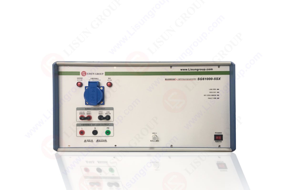

 中文简体
中文简体