
LM-79 Moving Detector Goniophotometer (Mirror Type C)
LSG-6000

High Precision Rotation Luminaire Goniophotometer
LSG-1890B

High Precision Rotation Luminaire Goniospectroradiometer
LSG-1890BCCD

Goniophotometer for Automotive and Signal Lamps
LSG-1950

Goniophotometer for Traffic Signal Lamps
LSG-1950S

Compact Goniophotometer
LSG-1200A

Near Field Moving Detector Goniophotometer
LSG-1900B
Select an organization
to browse standards
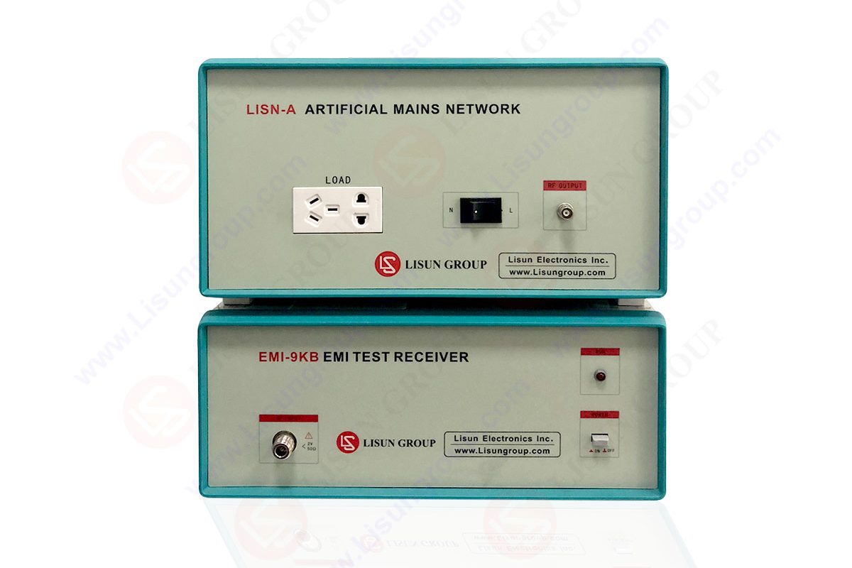
The calibration of an EMI analyzer happens to be one of the most significant processes in electromagnetic compatibility laboratories and particularly, high sensitivity EMC, where even the slightest error in measurements influences the compliance determination. Engineers use accurate measurements to determine the level of interference, source of emission and to determine the performance of a product. This is further ensured through high quality EMI testing equipment that makes this process even more reliable as all test instruments applied in the laboratory would work within the expected changes.
Calibration is not only a regulatory requirement; it is a technical basis that will ensure the accuracy and repeatability of all measurements of EMC. The paper will discuss some of the methods that can be used to calibrate, discusses the reasons that cause calibration in sensitive testing systems and present real-life information and examples that any engineer can use in the laboratory.
There are high sensitivity EMC environments, which are made to pick the smallest amount of interference. These laboratories typically require measurement of signals in the microvolt range and the low signal strengths of these instruments are easily affected by environmental noise, cable losses, component drift, and internal instrument aging. Due to this fact, frequent calibration of the EMI analyzer is obligatory so that the measurements are really relevant to the electromagnetic behaviour of the device in question.
Calibration done properly will further give an engineer confidence that the analyzer is displaying the correct amplitude, frequency, bandwidth, detector response, and noise floor levels. Radiated and conducted emissions are measured based on international CISPR and IEC standards, so the accuracy of the analyzer directly influences the results of compliance.
Table 1: Technical Factors For Calibration
| Factor | Description |
| Component aging | Internal parts like oscillators, filters, and amplifiers drift over time. Even a small drift of 0.5 dB can cause a borderline device to pass or fail incorrectly. |
| Environmental variations | Temperature, humidity, and electromagnetic noise from surrounding equipment affect measurements, especially in high sensitivity EMC setups. |
| Compliance requirements | Regulatory bodies typically require calibration every 12 months, while high precision labs may recalibrate every 6 months depending on usage. |
| Repeatability and traceability | Consistent measurements are possible only when equipment follows traceable calibration standards such as ISO 17025. |
By maintaining a routine calibration of the EMI analyzer, the laboratory can be comfortable reporting the level of emission and retaining the results up to the levels set by the regulations.
The most significant methods of calibration applied in modern EMC plants include:
1. Reference Level Calibration
Analysis stages and attenuators of the analyzer should be calibrated to some known calibration signal. The generator of the stable signal has a typically 50 ohms signal that inserts a known amplitude signal into the input at notable frequencies. The engineers check the reading in the analyzer and calibrate internal factors of the analyzer in case of deviations. To ensure work confidence in high-frequency work, the reference signal should have the uncertainty in less than 0.2 dB.
2. Frequency Accuracy Calibration
There is a possibility that the local oscillator of the analyzer can drift slightly. Measurement of frequency offsets is done and correction factors have to be applied. This holds special value when testing a narrowband interference as frequency error may misidentify sources of emission.
3. Noise Floor Verification
All EMI analyzers possess an intrinsic noise level variation with temperature, lifespan and individual component. Noise floor is both measured with an input short-circuited into a 50 ohm load. Any difference in the measured value exceeding 1 dB of the specifications of the manufacturer will result in the need to recalibrate the equipment. Sensitive EMC Highly sensitive EMC environments may demand extremely low noise floor in order to measure weak emissions.
4. Detector Mode Calibration
Quasi peak, average and RMS detectors should also be verified to check whether they are responding as required. In this calibration, repetition rate known modulated test signals are used. The output of each of the detectors is compared against calibration standard reference values. CISPR limits are very sensitive to detector type and thus good calibration of the detector is required.
5. Preselector and Filter Calibration
Band filters are installed in order to prevent overloading and to ensure the accuracy of measurements. All filters should be checked in regard to the accuracy of their insertion loss, selectivity and bandwidth. Filter loss drift of over 0.3 dB will cause a big change in emission measurements.
6. Linearity Testing
Linearity, ascertains that any variation in the input level is reproduced at the output in proportion. They do this by performing signal application to various power levels which are 40 dBuV, 60 dBuV and 80 dBuV. The analyzer should obey a straight response curve. The presence of nonlinearity signifies the loss of amplifier or mixer.
7. Antenna and Cable Verification
Antennas and cables are not internal to the analyzer, but will affect the calibration accuracy. A network analyzer is used to measure cable loss and reference test sites or calibrated databases of antenna factor are used to validate antennas. The accuracy of the data created by using well maintained EMI testing equipment is accurate across the entire measurement path.

Table 2: Common Calibration Parameters and Acceptable Tolerances
| Calibration Parameter | Typical Tolerance | Importance Level |
| Frequency accuracy | ±0.1 ppm | Critical |
| Amplitude accuracy | ±0.5 dB | High |
| Noise floor deviation | ±1 dB | High |
| Detector response accuracy | ±0.3 dB | Critical |
| Filter insertion loss | ±0.3 dB | High |
| Linearity deviation | ±0.5 dB | Critical |
These values usually appear in any professional EMC laboratory, and are well compatible with the system that LISUN offers, in line with internationally acknowledged calibration tolerances.
Calibration of EMI analyzer should depend on intensity of use and environment. A typical guideline is:
• Heavy usage environment
Calibration every 6 months
• Standard usage laboratory
Calibration every 12 months
• Critical aerospace or defense lab
Calibration every 3 to 6 months
Best practices include:
1. Maintaining a calibration logbook with the record of all the adjustments.
2. Warming up the analyzer at least 30 minutes and then start calibration.
3. Calibration should be avoided during unstable room temperature.
4. Checking related sources of amplitude and frequency with just certified sources.
5. It is also important to ensure that all the related EMI testing equipment is calibrated because mistakes could add up across all the devices.
These are the best practices that maintain accuracy, repeatability and the traceability standards.
The LISUN is reputed to offer high standard EMC reading systems with inbuilt calibration support functionalities. Most of their subscribers and analyzers have built-in calibration programs, optional reference sources of precision, and built-in programs to guide engineers during the calibration procedure.
A major characteristic of high sensitivity EMC environments is that practical EMI analyzer calibration is a critical factor because accuracy and repeatability matter in all decisions. The reliability of emission measurements and reduced probability of compliance failure can be enhanced by the working with high-quality EMI testing equipment and regular calibration. Regardless of the fact that the testing house is testing consumer electronics, automotive parts, medical apparatus or communication systems, regular calibration equates to reliable data. Engineers can ensure a reliable testing environment provided with the appropriate calibration practices as well as professional assistance of the manufacturer such as LISUN, and ensure the same EMC test results on all their products.
Lisun Instruments Limited was found by LISUN GROUP in 2003. LISUN quality system has been strictly certified by ISO9001:2015. As a CIE Membership, LISUN products are designed based on CIE, IEC and other international or national standards. All products passed CE certificate and authenticated by the third party lab.
Our main products are Goniophotometer, Integrating Sphere, Spectroradiometer, Surge Generator, ESD Simulator Guns, EMI Receiver, EMC Test Equipment, Electrical Safety Tester, Environmental Chamber, Temperature Chamber, Climate Chamber, Thermal Chamber, Salt Spray Test, Dust Test Chamber, Waterproof Test, RoHS Test (EDXRF), Glow Wire Test and Needle Flame Test.
Please feel free to contact us if you need any support.
Tech Dep: Service@Lisungroup.com, Cell/WhatsApp:+8615317907381
Sales Dep: Sales@Lisungroup.com, Cell/WhatsApp:+8618117273997

LISUN’s Motor-Operated Tool | Power Tool Testing solutions strictly comply with a range of core international standards, providing full support for safety and electromagnetic compatibility (EMC)...

LISUN’s transformer test solutions meet IEC 61558-1, IEC 60076-1, IEC 62041 standards. Covering safety, performance, EMC tests, ensuring transformers comply with global requirements.

LISUN’s household and appliance switch testing solutions meet IEC 60669, IEC 61058, IEC 62271 standards. Covering electrical, mechanical & EMC tests for global compliance.

For the CFL design and manufactory, LISUN can supply a full quality control test solution, including photometric, colorimetric, electricity, flicker, IES candela distribution, surge test, electrical...

 中文简体
中文简体