
LM-79 Moving Detector Goniophotometer (Mirror Type C)
LSG-6000

High Precision Rotation Luminaire Goniophotometer
LSG-1890B

High Precision Rotation Luminaire Goniospectroradiometer
LSG-1890BCCD

Goniophotometer for Automotive and Signal Lamps
LSG-1950

Goniophotometer for Traffic Signal Lamps
LSG-1950S

Compact Goniophotometer
LSG-1200A

Near Field Moving Detector Goniophotometer
LSG-1900B
Select an organization
to browse standards
Introduction
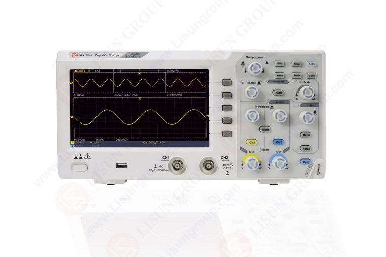
Digital oscilloscopes make it much easier for engineers to analyze and interpret the information contained in electrical signals. Design engineers have the potential to improve circuit functioning by learning more about signals, identifying problems, and using advanced methodologies for signal analysis.
In this piece, we’re going to look at the numerous ways in which digital oscilloscopes may be used for the study of signals. study of pulses and timing, in addition to study of frequency domains, will be investigated. If engineers are acquainted with these methodologies, they will be better equipped to assess signals, repair issues, and make design decisions.
Frequency Domain Analysis
The fundamental approach of signal analysis known as frequency domain analysis may be used to get information on the frequency content of a signal. Using digital oscilloscopes that are equipped with functionality for the Fast Fourier Transform (FFT), engineers are able to perform frequency domain analysis on waveforms that have been acquired.
When engineers take a waveform from the time domain and translate it into the frequency domain, they are able to determine the presence of harmonics, noise, and other frequency components. This research may be helpful in identifying signal distortions, defining signal spectra, and increasing the effectiveness of the system.
It is possible to compute the amplitude and phase of frequency components, which enables engineers to analyze the quality of a signal and guarantee that the signal’s frequency is within acceptable limits.
Time-Domain Analysis
Time-domain analysis is an essential tool that must be used in order to explore signal attributes and grasp signal behavior over the course of time. With the use of a digital oscilloscope, engineers are able to obtain a read on several aspects of a signal, including its rise and fall times, pulse width, duty cycle, and timing.
These observations give essential information about the signal’s intensity as well as its range and synchronization. Some of the issues that engineers may encounter include signal distortion, ringing, overshoot, and undershoot.
When assessing digital data, time-domain analysis is important for checking the smoothness of signal transitions as well as searching for outliers such as glitches and jitter. Both of these are examples of abnormalities.
Pulse and Timing Analysis
Pulse and timing analysis primarily focuses on doing investigations into the aspects of digital signals as well as the temporal links between those aspects. Digital oscilloscopes offer specific measurement and analysis capabilities, which enable users to conduct reliable analyses of pulses and timing. Timing in digital circuits may be monitored by measuring elements such as pulse width, period, rise/fall timings, and setup/hold periods, which engineers can use to fine-tune their designs.
Other measuring factors include rise/fall timings and setup/hold durations. These tests guarantee that signals are in sync with what is expected of them in terms of time. This is important for avoiding lost data or faulty circuits, which is why these tests are performed.
The accuracy of the pulse and timing measurements that are made possible by high-sampling-rate digital oscilloscopes is a significant contributor to the success of high-speed digital systems.
Eye Diagram Analysis
Eye diagram analysis is a powerful technique that may be used in high-speed communication systems to evaluate the quality of the signal as well as its dependability. In order to generate an eye diagram on a digital oscilloscope, several waveform acquisitions may be layered on top of one another.
The resulting form of an “eye” is a representation of the amplitude and phase changes that occurred in the signal during a certain period of time. Engineers may utilize eye diagrams in order to assess signal quality, quantifying parameters such as jitter and noise margins, and locating timing abnormalities or distortions.
Utilizing eye diagram analysis allows for the performance of high-speed digital interfaces to be assessed, equalization techniques to be enhanced, and reliable data transfer to be assured.
Power Analysis
The primary objective of power analysis is to examine the waveforms of the electrical power that flow through circuits and systems. Digital oscilloscopes that allow power analysis make it possible to measure several aspects of power, including power dissipation, power factor, harmonic content, and energy usage.
With the use of this research, one is able to determine whether or not power electronics systems are efficient, whether or not they are energy efficient, and whether or not they correspond to power quality regulations.
The impact of load changes on power waveforms may be analyzed by engineers, as can the detection of voltage sags and surges, as well as the identification of power anomalies.
Conclusion
When applying signal analysis techniques in conjunction with digital oscilloscopes, engineers have the potential to get a significant amount of knowledge on the properties of signals, the temporal correlations between signals, and the various features of the spectrum.
Electronics engineers have access to a wide range of studies, some of which are based on the frequency and time domains, pulse and timing, eye diagrams, and power, which they may use to evaluate and improve the operation of a circuit. Digital oscilloscopes equipped with extensive measuring capabilities and analysis tools allow for very accurate measurements to be performed of a signal’s frequency, amplitude, rise and fall times, pulse width, and power characteristics. These measurements may be done with amazing accuracy.
When engineers have a solid understanding of signals, they are better able to diagnose problems, determine whether or not certain timing criteria have been met, and ensure that electrical systems will perform reliably.
To summarize, digital oscilloscopes provide engineers access to a plethora of signal analysis capabilities, which enables them to conduct precise research on electrical waveforms and derive meaningful conclusions from such studies. Scientists and professionals may be able to understand more about the harmonics, noise, and frequency components of a signal by doing frequency domain analysis.
Time-domain analysis helps in the identification of anomalies and distortions, making it feasible to conduct accurate timing and signal integrity tests. This kind of analysis also makes it possible to quantify the signal’s inherent integrity. Engineers may check for erroneous data transmission by utilizing pulse and timing analysis to evaluate the synchronization of digital signals. This can be done in order to check for data transfer errors.
Eye diagram analysis is a method that may be used to analyze the effectiveness of high-speed communication networks. This method works by presenting a graphical representation of the signal’s quality. Engineers use a method called power analysis in order to optimize the use of energy, determine the quality of the power, and analyze the waveforms of the power.
By using these various techniques of signal analysis, engineers would be able to get a deeper understanding of the characteristics and characteristics of the signals that are present in electrical circuits. This information is essential for building systems that can be relied upon, locating and correcting faults, and achieving the highest possible level of circuit efficiency.
The comprehensive analytic capabilities and user-friendly interfaces of current digital oscilloscopes make it far easier for engineers to do the analyses and get actionable insights from recorded waveforms.
This is especially true in the case of the former. As technology advances, digital oscilloscopes will continue to be an essential tool for signal analysis. This gives engineers the ability to design electrical systems that are more sophisticated and reliable.
Lisun Instruments Limited was found by LISUN GROUP in 2003. LISUN quality system has been strictly certified by ISO9001:2015. As a CIE Membership, LISUN products are designed based on CIE, IEC and other international or national standards. All products passed CE certificate and authenticated by the third party lab.
Our main products are Goniophotometer, Integrating Sphere, Spectroradiometer, Surge Generator, ESD Simulator Guns, EMI Receiver, EMC Test Equipment, Electrical Safety Tester, Environmental Chamber, Temperature Chamber, Climate Chamber, Thermal Chamber, Salt Spray Test, Dust Test Chamber, Waterproof Test, RoHS Test (EDXRF), Glow Wire Test and Needle Flame Test.
Please feel free to contact us if you need any support.
Tech Dep: [email protected], Cell/WhatsApp:+8615317907381
Sales Dep: [email protected], Cell/WhatsApp:+8618117273997

 中文简体
中文简体