LM-79 Moving Detector Goniophotometer (Mirror Type C)
LSG-6000

High Precision Rotation Luminaire Goniophotometer
LSG-1890B

High Precision Rotation Luminaire Goniospectroradiometer
LSG-1890BCCD

Goniophotometer for Automotive and Signal Lamps
LSG-1950

Goniophotometer for Traffic Signal Lamps
LSG-1950S

Compact Goniophotometer
LSG-1200A

Near Field Moving Detector Goniophotometer
LSG-1900B
Select an organization
to browse standards
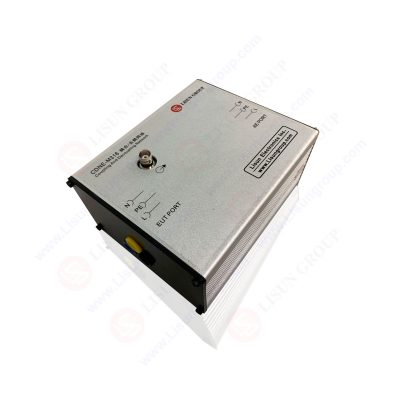
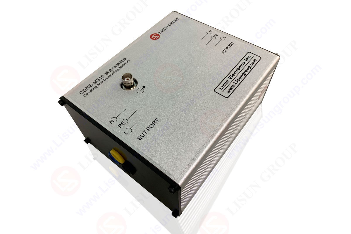
It is possible to do conducted immunity testing with the help of a coupling decoupling network (CDN). When connected to a generator, the CDNE-M316 will first cause a common mode disturbance into the EUT (EUT). An interference signal is sent to the EUT through the coupling network, which consists of cables and series conductors.
Most electrical equipment will also interact with other devices, called auxiliary equipment (AE) (AE). The decoupling network ensures that the generator’s disturbance signal won’t impact the auxiliary devices.
For repeatability and the security of all equipment other than the EUT, CDNs are favored in immunity testing. A coupling decoupling network guarantees the AE’s security, even during rigorous testing.
Despite their shared functionality, CDNs will create and test for various unique signals. Some types of coupling decoupling networks include RF sweep EMC immunity testing. Others will test transients like EFT/Burst, Surge, and others. To ensure your immunity testing complies with IEC/EN requirements, it is essential to choose the appropriate CDNE-M316.
Transient current distribution networks (CDNs) are tailored to handle EFT/Burst disturbances and pulse-shaped currents. When the coupling decoupling network is in use, the EUT, which is usually a device with higher voltages and currents, will be subjected to sudden surges.
When doing tests of immunity against disruptions caused by radio frequency waves, a special instrument called an RF CDN is required.
Description
Coupling Commonly abbreviated as “CDNs,” Decoupling Networks are used to both remove energy or disturbances (EMI/noise) and transmit them (coupling) (decoupling). Injecting noise that the EUT/DUT will be subjected to and then filtering out interference is a standard procedure in EMC immunity testing, where these are typically utilized.
A coupling decoupling network (CDN) is a device that isolates the EUT from the power sources and auxiliary equipment by superposing disturbances on power, communication, control, or similar lines connected to a EUT port (AE).
Since the IEC’s required immunity tests must be performed while the EUT is powered and operating, this kind of device is required. The same idea applies to the use of bursting disturbances on electricity lines.
A coupling device network (CDN) may send the generator’s disturbance directly to the EUT rather than the reverse.
The coupling network allows the disturbance to go down the EUT’s supply line but blocks the EUT’s power from entering the generator. EUT power can flow to the EUT via the decoupling network, but disturbance from the generator can’t make it to the power supply or the AE.
For this reason, a coupling decoupling network enables the application of disturbances to power EUT lines, effectively simulating the occurrence of disturbances in the power network as if they happened to owe to phenomena characteristic of these settings (power networks, communication lines, etc.).
Design
Each network will have its unique architecture and features based on the specific use case, related hardware, and underlying standard. CDNs have two primary benefits:

Figure: Coupling decoupling network
Where CDNs are used
Devices of this sort find employment in many contexts; two of the most frequent are RF (continuous) and transient immunity testing. CDNs are often used in both EMI testing forms, performed on a wide range of power and data (signal) lines.
It’s clear that the applications and line types significantly impact the structure of these CDNs. The networks are generally interchangeable across generator brands, as long as transient testing is not performed on the power mains.
There are numerous typical uses for CDNs, such as immunity testing and emissions testing, and the related frequency ranges are shown in the picture on the left.
Conducted RF Immunity CDNs
The most common injection technique for IEC 61000-4-6 testing is the use of CDNs made specifically for conducted RF testing. Additionally, they are the most effective injection device for RF immunity testing that has ever been developed. Most RF CDNs are built to IEC 61000-4-6 specifications, providing a common mode impedance of 150 Ohms.
Injection Efficiency
Compared to EM Clamps or BCI Probes, which provide the highest test levels with the least power, coupling decoupling networks are the most efficient injection technique. A significant increase in volume may be accomplished using CDNs, as shown in the accompanying chart when using either a 40-watt or 80-watt power RF amplifier.
CDN Selection
Due to the cable-specific nature of these networks, testing may need the usage of more than one at a time. The CDNs are compatible with several testing platforms, so you can choose the tools you need.
Types of RF CDNs
These subtypes are distinguished for use with certain connections and cables (IE, Coaxial, Unscreened, Etc.). The M Type series is the most popular since it is designed specifically for use with electrical wiring.
Even though there are terminals for the necessary lines, three-phase M-type CDNs are not usually suitable for single-phase EUT/DUT applications.
Testing using RF CDNs
The replacement approach is utilized in IEC 61000-4-6 testing independent of the injection device. Calibration information is a key component of this process since it establishes the baseline against which subsequent tests are conducted.
CDN Calibration Setup
RF systems perform a frequency sweep when calibrating and adjusting test levels to achieve the appropriate frequency level. Once the target is reached, the information is kept for further use in the evaluation process.
The CDNE-M316 injection technique used for the IEC 61000-4-6 calibration setup is shown below.
1) Conducted RF Test System
2) 100Ω Adapters
3) 6 dB Attenuator
4) Coupling Decoupling Network (CDN)
5) 50 Ω Termination Load
For test level calibration, a modular system must be set up, which involves connecting separate components and usually being managed by software.
Calibration Adapters
The 50 Ohm to 150 Ohm adapters is sometimes referred to as merely 100 Ohm adapters since they offer the 100 Ohm impedance necessary for IEC 61000-4-6. It is common practice to acquire a network alongside a shorting bar, which connects the CDN and the adapters.
Matching adapters, or shorting adapters, are specific to a certain network’s line setup and are thus not always interchangeable. Adapters in the 100 (50 to 150) range may be acquired from LISUN or elsewhere online.
A short and 50 Ohm to 150 Ohm adapters are shown linked to a content delivery network in the accompanying illustration.
1) Shorting Adapter 5 Lines
2) Associated 5 Line CDN
3) 50 to 150Ohm Adapters
4) Shorting adapter connected
Transient Immunity CDNs
Electrical fast transients(EFT)/Bursts, and combination wave surges (IEC 61000-4-5), are the most prevalent transient pulses that need coupling decoupling networks (IEC 61000-4-4). Different content delivery networks (CDNs) are needed for each, and surges need specific attention because of the pulse line sync requirements.
Automatic & Manual Couplers
Over 16 amps of three-phase electricity require a manual or automated coupler for surge testing. Systems often include CDNs with loads below 16 Amps on a single phase.
Unlike manual couplers that need to be adjusted to satisfy the same requirements, automated CDNs allow modifications up to a specific threshold and coupling configuration. In many cases, manual methods do not allow for threshold selection, which greatly restricts the available possibilities.
Combination Wave Surge CDNs
Part of the way that surge generators create transients is by injecting them directly into various lines, most often electricity mains. It must maintain line synchronization given the phase angle requirements of 0, 90, 180, and 270 degrees at the CDNE-M316 output (IEC 61000-4-5).
The pulse may be positioned on the desired phase angle thanks to the two-way communication between the generator and its matching coupling decoupling network. The graphic shows how the location could appear on a standard AC mains sine wave, which is a prerequisite of surge testing.
EFT/Burst CDNs
IEC 61000-4-4 is widely used to test fast electrical transients (EFT), including testing on both data and power main lines. Due to the rapid succession of short pulses, this EMI event is also known as a burst. This burst of signals does not have any strict phase angle limitations, making it easier to combine different pieces of technology.
Surge and EFT capabilities are often found in the same CDNs, making it straightforward to test both. Rather than spending time switching out couplers and disconnecting the equipment being tested, this is generally seen with automated CDNs, which allow for efficient testing.
CAPACITIVE COUPLING CLAMPS (CCLS)
When it comes to coupling EFT/Burst pulses onto data or communication, CCLs are a great option since they eliminate the need to worry about using cables of the same kind. It may utilize these gadgets interchangeably if they are connected properly to their respective transient generators. Coupling clamps do not have any decoupling capabilities and just couple the pulses onto the data lines.
To ensure that the test equipment is compatible with one another, the coupling decoupling network (CDN) couples or decouples RF signals to/from cables that are physically connected to the test apparatus (EMC). This method is the benchmark for testing for immunity and is recommended by IEC61000-4-6. It is also possible to use CDNs to measure emissions for EN55022 compliance.
Immunity testing
CDNs are the best coupling and decoupling devices because they ensure test repeatability and the security of auxiliary equipment (AE). CDNs are used for correct coupling of the disruptive signal to the various cables attached to the tested equipment, preventing the signal from affecting other devices, equipment, and systems (EUT).
Emission testing
CISPR 15 and CISPR 22 mandate that CDNs submit to emission testing across a wider frequency range (80 MHz to 300 MHz), and several CDNs already do so.
The common mode impedance and the frequency response of the voltage division factor up to 300 MHz are supplied.
An adjustment of the EUT port voltage on the CDN’s output.
Below, you’ll find the assembly instructions.
With direct injection to screened cable, 150 ohms load at the AE-port is not required since it will connect the screen to the ground reference plane on that side (CDN-S kinds).
Calibration values for CDN M-types, CDN AF-types, and CDN T-types are mostly immune to load variations, despite their widespread use of the 150-ohm connection. Like the S-types, they have capacitors against the ground on the AE-port side, which results in a short circuit and a loss of RF signal.
This way, the 150-ohm load at the auxiliary equipment connection is unnecessary for the CDN M-type, CDN AF-type, and CDN T-type.
Frequency range
The standard specifies standards for the frequency range of 150 kHz to 80 MHz. However, the appropriate frequency range depends on the equipment being evaluated’s typical installation and operating circumstances. It has been decided that 80 MHz will be the standard cutoff frequency.
Specific product specifications may need a higher cutoff frequency, as high as 230 MHz, in the case of small-sized equipment.
The size of the equipment, the interconnecting cables utilized, the availability of specific CDNs, and so on all impact the findings when applying this test technique up to higher frequencies. It may find further instructions in the designated product standards to ensure correct implementation.
Lisun Instruments Limited was found by LISUN GROUP in 2003. LISUN quality system has been strictly certified by ISO9001:2015. As a CIE Membership, LISUN products are designed based on CIE, IEC and other international or national standards. All products passed CE certificate and authenticated by the third party lab.
Our main products are Goniophotometer, Integrating Sphere, Spectroradiometer, Surge Generator, ESD Simulator Guns, EMI Receiver, EMC Test Equipment, Electrical Safety Tester, Environmental Chamber, Temperature Chamber, Climate Chamber, Thermal Chamber, Salt Spray Test, Dust Test Chamber, Waterproof Test, RoHS Test (EDXRF), Glow Wire Test and Needle Flame Test.
Please feel free to contact us if you need any support.
Tech Dep: Service@Lisungroup.com, Cell/WhatsApp:+8615317907381
Sales Dep: Sales@Lisungroup.com, Cell/WhatsApp:+8618117273997

 中文简体
中文简体