LM-79 Moving Detector Goniophotometer (Mirror Type C)
LSG-6000

High Precision Rotation Luminaire Goniophotometer
LSG-1890B

High Precision Rotation Luminaire Goniospectroradiometer
LSG-1890BCCD

Goniophotometer for Automotive and Signal Lamps
LSG-1950

Goniophotometer for Traffic Signal Lamps
LSG-1950S

Compact Goniophotometer
LSG-1200A

Near Field Moving Detector Goniophotometer
LSG-1900B
Select an organization
to browse standards
The International Electrotechnical Commission (IEC) standard IEC61000-4-12, EN61000-4-12, ANSI-C62-41, and GB/T17626.12 were taken into consideration when designing the Ring Wave Test Generator. This device is used to simulate an electrical network, give power to reactive loads and regulate line switches. A ring wave generator also senses low voltage cable terminal equipment rings that are generated by power circuit disconnections, insulation failures, and lightning strikes. The LCD displays on the RWG61000-12 series products are available in Chinese and English. This article is a detailed explanation of what LISUN’s ring wave generator is, it’s working, and functionality in addition to a brief writeup on conducting different tests using it.
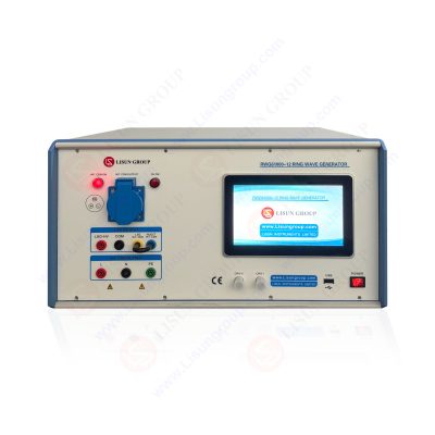
Ring Wave Generator | RWG61000-12|
A ring wave generator offers high-end combination or single function solutions that are compliant with national, international, and manufacturer’s standards like IEC/EN 61000-4-12 and ANSI C62.41 & 45 for replicating Ring Wave pulses for immunity testing. The gadget, one of LISUN’s distinctive pieces of technology, is used to simulate an electrical network, supply power to reactive loads, operate control lines, and detect ring waves in low-voltage cable terminal equipment brought on by electrical faults, insulation failures, and lightning strikes. The LCD displays on the RWG61000-12 series products are available in Chinese and English.
 be used in the most effective manner 1")
Ring Wave Generator RWG61000 12 AL
The ring wave is an oscillating transient that develops in low-voltage cables as a result of reactive loads switching, failures, and insulation breakdown in power supply circuits or lighting, as well as switching of electrical networks. The ring wave generators required for the EN/IEC 61000-4-12 immunity test are kept in stock and are available for rental or purchase at the EMC Shop.
Product detail
The output voltage range of the ring wave generator’s RWG61000-12 ring model is 0 to 4 KV. With a boundary of 0.5 s and 20%, its voltage/current waves are essentially open circuit voltage waves. The wavefront of a short circuit current is one second. The oscillation frequency of the gadget is 100 kHz + 10%. Additionally, it might have a positive, negative, or automatic positive/negative polarity. The phase shift is asynchronous or synchronized at an angle between 0° and 360°. The output impedance of the RWG61000-12 is 12 or 30. A single phase 16A device coupling/decoupling network (CDN) is included.
Last but not least, it operates on AC220V (Option 110V) 10%, 50/60Hz. The device’s D*W*H measurements are 44*45*35cm, and its gross weight is around 28kg. The fact that it also features a Super large LCD touch screen and built-in Windows CE is a crucial point to remember. The generator also includes a pulse-forming network, a high-voltage/high-current switch, an energy storage capacitor, an electronically regulated high-voltage power supply, and a control- and monitoring unit.
The user interface and display unit of the Ring Wave Generator are controlled by a microprocessor for convenience. The microprocessor enables the user to run either common test routines or a test sequence that has been “user specified.” The rotary encoder allows for simple adjustment of the test settings, which are displayed on the built-in display. While testing is being done, a summary of the test parameters can be printed using a conventional parallel interface.
Additionally, using the separated optical interface, all generator operations, including the configuration of the built-in Coupling-/Decoupling Network, may be computer controlled. The I software package enables complete remote control of the test generator as well as the recording and analysis of test results. The generator excels due to its small size, straightforward operation and the precision of its test results.
Test Procedure
The voltage circuits are first energized with their highest specified nominal voltages. The length of the connection wire is set at 1 m. Next, a high-resolution read of the active- and reactive SUM registers is performed. The readings are required subsequently for the Pass/Fail assessment.
The fundamental AC voltage waveform at phase angles of 0°, 90°, 180°, and 270° must be used in all subsequent testing along with transients (our ring wave). At each designated phase angle, five positive and five negative transients must be applied at a rate of one per minute. Therefore, each of the following tests will take 40 minutes to complete. For a direct connection, three-phase, four-wire meter, the tests are given.
Test of the Main Meter Terminals
The generator’s impedance is set to 12. After that, a 4 kV test is conducted between each line, including neutral, and ground. We close the disconnection relay and remove the mains-in terminals. 160 minutes total, not including wiring changes.
Also we are currently evaluating each line to line and each line to neutral with 12 and 2 kV in differential mode. Means:
L1 versus L2, L1 versus L3, and L1 versus N
L2 versus L3, L2 versus N, and L3 versus N
This set will cover all scenarios for our three-phase four-wire meter because we are testing with both polarities. There is 240 minutes total, excluding the wiring replacement.
HLV Signal Ports
Hazardous Live Voltage is the abbreviation. These voltages exceed 33 V RMS according to IEC 62052-31. Terminals for external relay control are an example of an auxiliary input- or output circuit. You must be certain of the voltage terminal ratings prior to doing the tests. The tests must be conducted using 12 and 2 kV between each line and the ground. It must also be conducted using line between lines with 12 and 1 kV in differential mode. Only the differential mode is used to test potential-free connections.
 be used in the most effective manner 2")
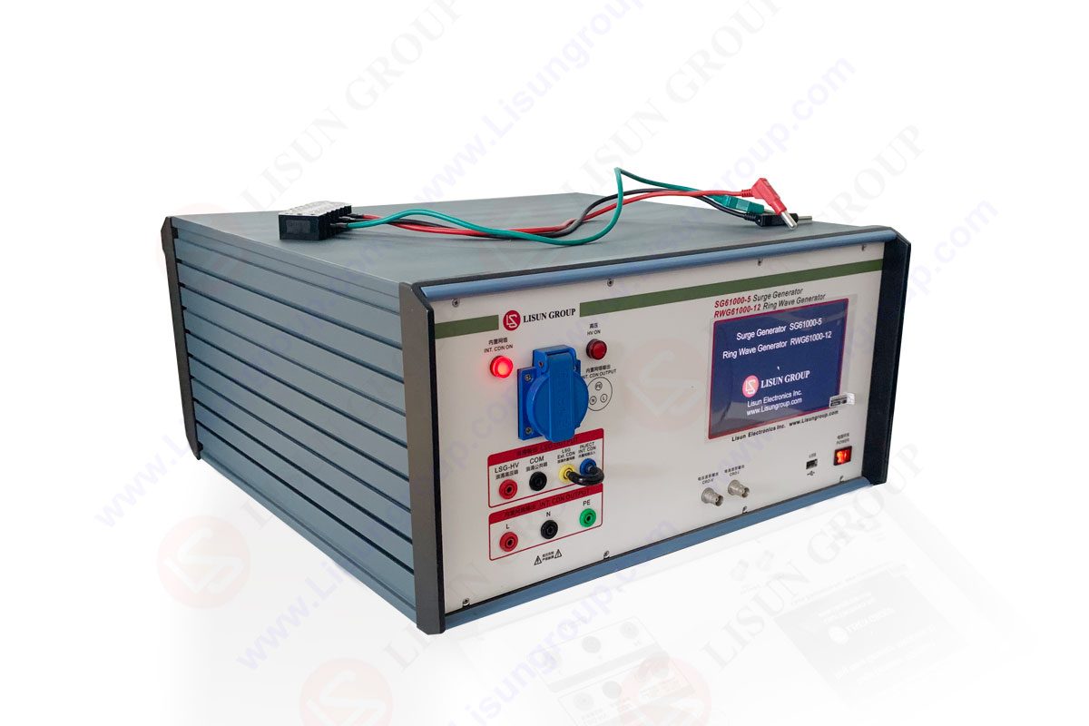
RWG61000-12 Ring Wave Generator
ELV Signal Ports
Extra Low Voltage is referred to as ELV. These are the terminals of circuits with auxiliary input or output, data communication, and other circuits with voltages lower than 33 V RMS. Common mode testing is carried out using 30 and 0.5 kV. The term “common mode” refers to synchronous coupling to every line and the ground.
Building two signal groups are as follows:
Pass/Fail Evaluation
It’s permissible for primary functionalities to temporarily deteriorate or cease operating throughout the test:
The meter must show no signs of damage and must operate with an additional percentage error that does not exceed the limits stated in the pertinent particular requirements (accuracy class) standards after the test, once the disturbance has been eliminated and the reference test conditions have been restored.
Without any operator intervention and without cutting off the mains supply or the auxiliary power supply, all meter functions covered by this document must be restored. This means that before turning off the ring wave generator station, you must do the function tests there. It’s good that the IEC makes this final statement.
RCCBs’ Ring Wave Test
Residual Current Operated Circuit Breakers (RCCBs) can be tested using the Ring-Wave Generator IPG 612T in accordance with IEC 1008.Each current path of the RCCB is loaded with a ring wave current during this test. A 250 A peak current value does not necessarily trigger the RCCB. In order to monitor the output current, this option also involves modifying the generator and adding an additional current watching resistor (View Figure 1).For testing Residual Current Operated Circuit Breakers (RCCBs) in accordance with IEC 1008, the Ring-Wave Generator IPG 612T can be modified as follows:
Connecting the specifically created SHUNT to the output terminals enables modifications 1 and 2. The RCCB’s protective earth terminals must be linked to the terminal COM’. See Options for further accessories.
Ring Wave Test of RCCBs with Safety Test Coverage
Residual Current Operated Circuit Breakers (RCCBs) can be tested using the Ring-Wave Generator IPG 612T in accordance with IEC 1008. Each current path of the RCCB is loaded with a ring wave current during this test. The RCCB may not be triggered up to peak current values of 250 A. In order to monitor the output current, this option also involves modifying the ring wave generator and adding an additional current watching resistor.
The COM terminal is linked to GND in step one.
FAQs
What is the basic use of LISUN’s ring wave generator?
This device senses the ring wave of the low voltage cables terminal equipment caused by the disconnection of the power circuit, a fault, insulation breakdown, or a lightning strike. It is also used for the simulative electrical network, the power supply of the reactive load, and the control line switch.
What are some of the main components of the ring wave generator?
The ring wave generator is made up of a pulse-forming network, a high-voltage/high-current switch, an energy storage capacitor, an energy storage capacitor with electronic regulation, and a control- and monitoring unit. A Coupling-/Decoupling Network (CDN) for single-phase power supply lines is also included with the ring wave generator. A built-in optical interface controls external coupling-/decoupling networks for 3-phase power supply lines.
Lisun Instruments Limited was found by LISUN GROUP in 2003. LISUN quality system has been strictly certified by ISO9001:2015. As a CIE Membership, LISUN products are designed based on CIE, IEC and other international or national standards. All products passed CE certificate and authenticated by the third party lab.
Our main products are Goniophotometer, Integrating Sphere, Spectroradiometer, Surge Generator, ESD Simulator Guns, EMI Receiver, EMC Test Equipment, Electrical Safety Tester, Environmental Chamber, Temperature Chamber, Climate Chamber, Thermal Chamber, Salt Spray Test, Dust Test Chamber, Waterproof Test, RoHS Test (EDXRF), Glow Wire Test and Needle Flame Test.
Please feel free to contact us if you need any support.
Tech Dep: Service@Lisungroup.com , Cell/WhatsApp:+8615317907381
Sales Dep: Sales@Lisungroup.com , Cell/WhatsApp:+8618117273997

LISUN’s energy meter testing solutions align with IEC 62052-11, IEC 62053 series standards. Covering safety, electrical, environmental, and EMC tests, we help manufacturers meet global compliance...

 中文简体
中文简体