LM-79 Moving Detector Goniophotometer (Mirror Type C)
LSG-6000

High Precision Rotation Luminaire Goniophotometer
LSG-1890B

High Precision Rotation Luminaire Goniospectroradiometer
LSG-1890BCCD

Goniophotometer for Automotive and Signal Lamps
LSG-1950

Goniophotometer for Traffic Signal Lamps
LSG-1950S

Compact Goniophotometer
LSG-1200A

Near Field Moving Detector Goniophotometer
LSG-1900B
Select an organization
to browse standards
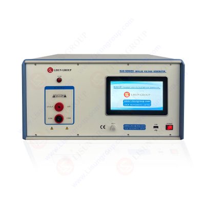
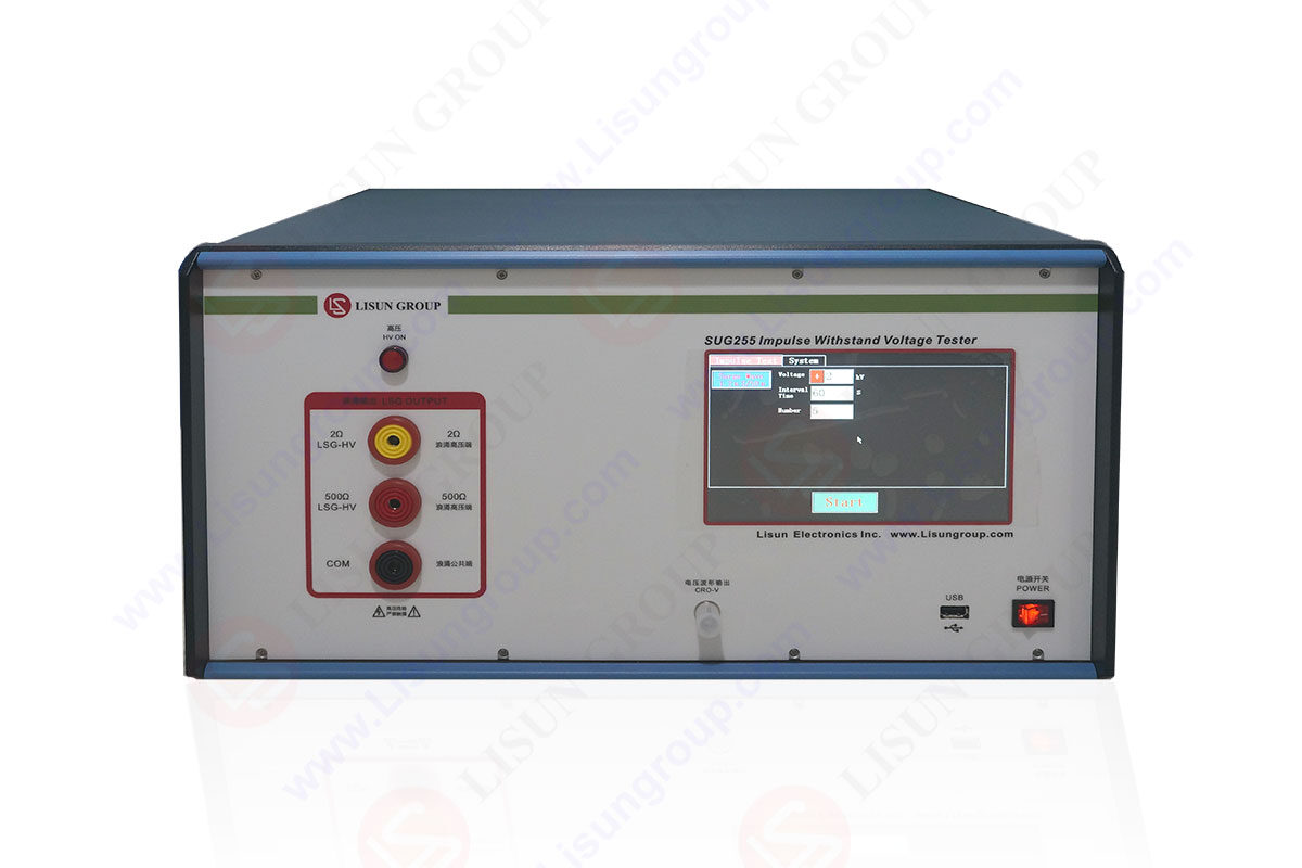
A device that generates very brief spikes in voltage or current is known as an impulse generator SUG255. It may break down these gadgets into two categories: impulse voltage and current generators.
Lightning and switching surges may damage electrical infrastructure. Thus it’s important to evaluate its resilience using high impulse voltages. Some nuclear physics experiments even make use of steep-front impulse voltages.
Not only do technologies like lasers, thermonuclear fusion, and plasma devices need high impulse currents for testing, but so do many others.
Impulse generators
Power surges pose a significant problem for every electronic device and are every circuit designer’s worst fear. The term “impulse” is widely used to describe these spikes in voltage, which are normally measured in the kilovolt range and last for just a few microseconds.
Lightning is an example of a natural phenomenon that generates impulse voltage, which can identify by its distinctive high or low fall time followed by a very high-rise time of voltage. Our products must be tested for resilience against impulsive voltage since it may cause catastrophic failure in electrical equipment.
Here, a device called an impulse voltage generator produces short bursts of very high voltage or current inside a carefully monitored testing environment. The purpose and operation of an Impulse Voltage Generator are discussed here. Consequently, let’s get into action.
As was previously mentioned, an impulse generator creates very brief, extremely high-voltage, or high-current surges. As a result, there are two distinct impulse generators: those that produce a voltage spike and those that have a current wave. But here, we’ll talk about impulse voltage generators.
Impulse voltage generator
A set of capacitors, resistors, and spark gaps make up an impulse voltage generator. After being charged in parallel through resistors from a high-voltage direct-current source, the capacitors are connected in series and discharged via a test item via a simultaneous spark-over of the spark gaps.
The spark gap discharges the impulse current via resistances, inductances, and the item under test. The current impulse generator comprises numerous capacitors that are charged in parallel by a high-voltage, low-current, direct-current source.
Transformer testing, impulse current testing of surge arresters, and even components of wind turbines or airplanes are specialized tests that may be performed using customized impulse voltage generators. Because of the system’s modular nature, it may use in various settings, including manufacturing and research & development facilities.
Marx generator
Among them is the Marx generator because Erwin Otto Marx initially suggested it in 1923. Multiple capacitors are charged in parallel using resistors, simulating a high-voltage direct-current source, and then linked in series and discharged via a test item with a single spark across the spark gaps.
The spark gap discharges the impulse current via resistances, inductances, and a test item in parallel after being charged by a high-voltage, low-current, direct-current source.
Circuit of the impulse generator
The impulse voltage generators use a tweaked version of the Marx multiplier circuit. As the generator progresses through its phases, positive and negative DC voltages up to 100 kV are applied across spark gaps connecting the generator’s array of impulse capacitors in series, generating electrical impulses.
The front and tail resistors in the generator stages allow for fine-tuning the rise and fall times of the roughly double-exponential impulses. Internal inductances are kept low, and voltage is shaped smoothly by keeping the discharge loop short.
Components of the impulse voltage generator
Four glass-fiber reinforced plastic columns provide insulation for the impulse generator’s internal components. Each generator stage is structurally sound, thanks to rectangular frames. Each third stage has a collapsible platform that it may access to swap out the resistors.
An insulated ladder provides safe access to these platforms at the generator’s phases. To ensure that the switching spark gaps throughout all stages always have clean air for reliable triggering, they are often housed in a fifth insulating column with a small air over-pressure.
The test generator’s safety features include two earthing switches, and two motor-operated earthing ropes, which short-circuit all impulse capacitors when the impulse generator is turned off.
LISUN has the best quality impulse generator for impulse voltage testing.

Figure: Impulse generator
Construction of impulse generator
It must charge the impulse capacitance C1 of an impulse generator SUG255 from a direct current (DC) source. A rectifier and step-up transformer form the supply. To prevent pre-stressing effects inside the insulations from affecting the breakdown strength, charging durations should be at least 3 to 10 seconds long. This is because each voltage application leaves behind pre-ionizing effects.
Charging via thyristors regulated DC source is now a practical option. Various resistive materials, including wire, liquid, and composites (carbon, etc.), may be used to construct the resistors.
Thus, the comparatively expensive non-inductive wire-wound resistors are utilized for this purpose. From the perspective of circuit oscillation, they are considered fairly adequate.
These resistors should be positioned so that can be quickly swapped out for new ones since their charging needs may vary depending on the wave produced. The capacitors chosen for usage in an impulse generator significantly impact its design.
Conventionally, high-discharge-rate capacitors with oil paper insulation are used. It is common practice to substitute the material oil with special fluids with greater permittivity to achieve the same capacitance with a smaller capacitor.
One benefit of this design is that it allows for stacking capacitors in a vertical column. Each stage is separated from the next by supports that mimic the shape of the capacitors but lack the dielectric.
The gaps between the connection spheres are stacked horizontally on arms and are changed using a motor and an indicator under remote control. The spark gaps cascade perfectly with this configuration thanks to their mutual irradiation.
When using the right gas mixes, switching performance improves. When the impulse generator is not in use, the capacitors need to be discharged to the ground. Due to the relaxation phenomena, DC capacitors may rapidly accumulate large voltages after being short-circuited for a brief period.
Procedure
Here is the full procedure explained well.
Features of the impulse voltage generator
Applications of the voltage impulse generator
The primary use for the impulse generator SUG255 circuit is testing high-voltage devices. The Impulse voltage generator is used to test a variety of surge protectors, including lightning arresters, fuses, diodes, and other kinds of surge protectors.
Not only is the impulse generator circuit useful in the testing industry, but it is also vital equipment used in nuclear physics investigations and the industries of lasers, fusion, and plasma device manufacturing.
Modeling lightning’s impacts on power-line gear and aviation industries is accomplished with the assistance of the impulse generator. In addition to that, it is used in X-Ray and Z-machines. Impulse generator circuits are also used for testing various applications, including the insulation of electrical components.
It may simulate lightning strikes and switching surges with impulse testing devices, which can generate impulse voltages in rapid succession. IEC, ANSI/IEEE, and other national standards outline the scope of these applications.
Similarly, current impulse generators, or “Impulse Test Sets,” are widely available for use in testing surge arrestors. Impulse test equipment for the electromagnetic compatibility (EMC), avionics, and defense sectors has been supplied by LISUN for many years.
Other applications
Here you will find many other applications of an impulse generator.
Benefits of using impulse generator
Lisun Instruments Limited was found by LISUN GROUP in 2003. LISUN quality system has been strictly certified by ISO9001:2015. As a CIE Membership, LISUN products are designed based on CIE, IEC and other international or national standards. All products passed CE certificate and authenticated by the third party lab.
Our main products are Goniophotometer, Integrating Sphere, Spectroradiometer, Surge Generator, ESD Simulator Guns, EMI Receiver, EMC Test Equipment, Electrical Safety Tester, Environmental Chamber, Temperature Chamber, Climate Chamber, Thermal Chamber, Salt Spray Test, Dust Test Chamber, Waterproof Test, RoHS Test (EDXRF), Glow Wire Test and Needle Flame Test.
Please feel free to contact us if you need any support.
Tech Dep: Service@Lisungroup.com, Cell/WhatsApp:+8615317907381
Sales Dep: Sales@Lisungroup.com, Cell/WhatsApp:+8618117273997

LISUN’s transformer test solutions meet IEC 61558-1, IEC 60076-1, IEC 62041 standards. Covering safety, performance, EMC tests, ensuring transformers comply with global requirements.

LISUN’s energy meter testing solutions align with IEC 62052-11, IEC 62053 series standards. Covering safety, electrical, environmental, and EMC tests, we help manufacturers meet global compliance...

LISUN’s audio-video communication testing solutions meet CISPR 13, IEC 60065, FCC Part 15 & EN 55032. Cover EMC, safety & performance tests for reliable AV equipment...

LISUN’s household and appliance switch testing solutions meet IEC 60669, IEC 61058, IEC 62271 standards. Covering electrical, mechanical & EMC tests for global compliance.

 中文简体
中文简体