
LM-79 Moving Detector Goniophotometer (Mirror Type C)
LSG-6000

High Precision Rotation Luminaire Goniophotometer
LSG-1890B

High Precision Rotation Luminaire Goniospectroradiometer
LSG-1890BCCD

Goniophotometer for Automotive and Signal Lamps
LSG-1950

Goniophotometer for Traffic Signal Lamps
LSG-1950S

Compact Goniophotometer
LSG-1200A

Near Field Moving Detector Goniophotometer
LSG-1900B
Select an organization
to browse standards
Based on the junction temperature measurement method of high power LED, the ratio of current amplitude to workflow during injection of square wave current pulse into the measured LED device is studied. It is found that the ratio of actual rated current to impulse current is the same. The junction temperature of the LED can be measured by directly measuring the forward junction voltage of the LED under the rated working current and assisting the temperature sensitivity coefficient.

T5_LED Thermal and Electrical Performance Analyzer
1. Introduction
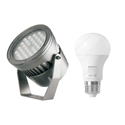
The level of LED junction temperature has a great relationship with its packaging. Our country’s multi-chip integrated packaging is currently one of the most feasible solutions to obtain high luminous flux. In the actual application process, the utilization rate is greatly reduced due to the constraints of related prices, the space available for the LED integrated package, and the heat dissipation problems. In the actual application process of light-emitting chips, because the density is too concentrated, it is likely to cause heat dissipation problems of the product, resulting in a sudden increase in the temperature of the substrate. Therefore, for such problems, it should be packaged by changing the structure of the heat sink.

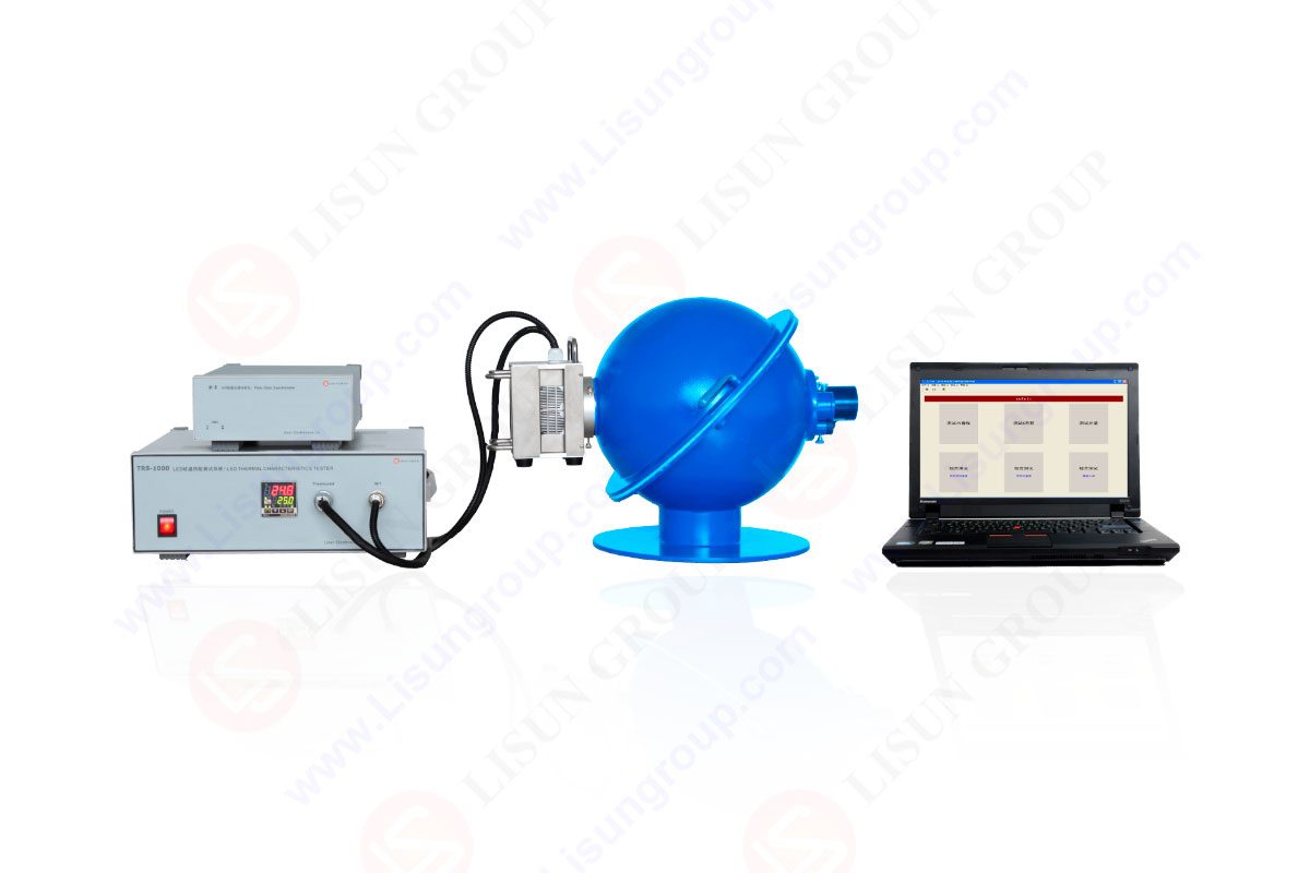
TRS-1000_Thermal Resistance Spectroradiometeric System for LED
2. Research on thermal characteristics of LEDs
2.1 Influence of drive current
The LED junction temperature can be understood as the value of the LED chip temperature. Generally speaking, there are various reasons for LED junction temperature. There are two major factors: on the one hand, due to the low light extraction efficiency, the application efficiency of LEDs in energy conversion is low, and the resulting junction temperature changes; second, it is caused by the low heat dissipation capacity of the LED package. The lower the heat dissipation capacity, the lower the light extraction efficiency and the higher the junction temperature rise.
2.2 Influence of junction temperature on LED parameters
(1) Permanent aging of LED. When the LED junction temperature is under high temperature, the aging is very serious, because this permanent aging cannot be recovered. At high temperatures, the LED package suffers from a reduction in optical efficiency.
(2) Interference to LED forward voltage. During the rise of LED junction temperature, due to the influence of temperature at this time, the voltage value VF value will drop significantly compared with the peak value. Therefore, LEDs have a negative temperature coefficient characteristic when IF is constant. Then, as the intensity of the disturbance increases, so does the P-N junction temperature. In practical applications, constant current power supply is the optimal mode for LED operation. Due to the interference of such forward voltage, the forward current increases which will damage the internal components of the product.
(3) Interference with LED light-emitting wavelength. When the junction temperature rises, the emission wavelength of the LED becomes longer. At this time, the color cast light emission wavelength of the LED display effect can generally be divided into two categories: peak wavelength and dominant wavelength. These two categories represent the dominant wavelength and the intense light wavelength, respectively. The X and Y chromaticity coordinates determine the perceived color of the dominant wavelength, and the band gap value of the material in the light-emitting region plays a decisive role in the wavelength or color of an LED device.
(4) Interference with LED light efficiency. As the junction temperature continues to rise, problems such as dislocation structure defects will occur in the product. Once the temperature rises to the maximum over time, it is likely to cause a sudden drop in luminous flux, which will cause serious damage to the equipment.
(5) Interference with LED phosphor efficiency. The junction temperature change of LED chips is more complicated. In this process, as the problem of LED phosphor efficiency interference continues to aggravate, the luminous efficiency of LED phosphors will eventually decrease, but in general, it will not cause serious damage to the application of the product.
3. LED junction temperature measurement technology
At this stage, my country has not formed a standardized and unified measurement standard for LED junction temperature measurement technology. In the LED junction temperature measurement technology, due to the inconsistency of process and other factors, and the lack of a strict relevant standard in practical applications, this makes the measurement of high-power LED junction temperature problematic, and if it is compared with traditional power, it can be found , the two are quite different.
(1) Application of infrared thermal imaging method. This imaging method measures the LED junction temperature, which has the advantage of convenient measurement in practical application. However, at the same time, there is also the disadvantage of being easily affected by the LED package structure in practical applications, resulting in certain measurement errors. Moreover, the instruments to which this method is applied are expensive.
(2) The application of spectroscopy. This method mainly uses that when the LED junction temperature rises, the dominant wavelength of the LED will change to a certain extent, and this change will cause the wavelength to drift. When the dominant wavelength drifts, the wavelength shifts to the long wavelength by about 1 cm for every 10 °C increase in the junction temperature.
(3) Application of pin temperature method. The pin temperature method is also very common in current applications. This method can finally determine the junction temperature of the thermal power dissipated by the chip mainly by virtue of the thermal transport properties.
(4) Application of blue-white ratio method. The blue-white ratio method is a non-contact junction temperature measurement method. The biggest advantage of this method is that in practical applications, the actual junction temperature can be directly measured without destroying the whole with this method. numerical value.
(5) Application of pulse current method. The application of pulse current is more common in the industrial field. The amplitude of this method is the actual rated current value of the LED. Through the measurement of the high-speed voltage sampling circuit, the forward voltage value of the LED square wave current pulse input can be grasped. In the actual application process, the influence of the current pulse on the LED junction temperature can be temporarily ignored, and the final sensitivity coefficient can be measured.
4. LED pulse current method test
(1) Measuring device. The measurement device is widely used in the LED pulse current method. Among them, the adjustable pulse signal source of the measurement device can produce a pulse signal; the application of the measurement device increases the selectivity of pulse transformation, and the circuit is responsible for the classification of the output of the pulse signal source certain changes. Because the application of the measuring device can control the voltage of the front stage, the voltage-controlled current source outputs a certain value of pulse current according to the requirements. The incubator is responsible for providing a relatively stable measurement environment for LED measurement.
(2) Analysis of parameter characteristics. The T5 has many advantages in practical application, and these advantages are mainly reflected in the recording of junction temperature data. At the same time, the application of can also avoid damage to the device due to excessive junction temperature. If during operation, when the supply voltage is lower than 10 V, theT5 can also automatically terminate the working state to protect the circuit.
(3) Controllable pulse current source circuit. This article mainly refers to the typical working circuit of T5, and takes it as a typical application case of the controllable pulse current source circuit. The results show that: when the pulse frequency of the controllable pulse source reaches a certain pulse width, the source circuit of the controllable pulse current can also ensure the invariance of the original waveform. When changing the current in the circuit, first of all It conducts sampling analysis, at this time, the rise time of the controllable pulse power supply current will be slightly greater than 1 µs. However, it can be found by comparison that although the original waveform has changed, the change of the waveform has no effect on the working circuit. From this, it can be known that RP1 in the circuit can adjust the peak current value of the pulse wave, so that the valley current of the current source can reach “0” as much as possible, and the function of RP2 can balance the residual valley voltage of the 74LS00 gate circuit, and it can also adjust The valley current of the current source makes it a certain desired current value.
(4) Test process. Calculate the junction temperature value and thermal resistance value. In the experiment, the junction temperature of the sample LED was measured by the small current K-factor method and the narrow pulse method under the same working state. Run the LEDs with the current working for a long time, and then measure the current operation separately. The application of the small current K-factor method and the narrow pulse method is mainly to ensure the accuracy of the experiment and the accuracy of the experimental data. The specific response data are shown in Table 1. The analysis found that there is a relationship between the data of the junction temperature value and the data of the thermal resistance value.
(5) Experimental results. It can be seen from the experimental data that although this method is still in further experiments, there are still some problems in the experimental results, and the main problem is that the requirements of the voltage-controlled current source have high standards. At the same time, the pulse signal source has high requirements, especially for the response rate of the voltage-controlled current source in the test, which has extremely high requirements and standards.
5. Conclusion
(1) Through theoretical analysis of the above-mentioned relevant thermal parameters. It can be found that in the course of the experiment, the factors affecting the pulse current measurement value of the LED junction temperature include the measurement steps, the pulse width, and the accuracy of the measurement value.
(2) Use the pulse current method to test the actual situation of the LED junction temperature, and use the high-speed controllable square wave pulse current source to measure the LED junction temperature as the main idea during the experiment, which can effectively guarantee the accuracy of the experiment, and at the same time It also brings theoretical help to the real design and manufacture of instruments for measuring junction temperature by pulse method. Due to the short period of the experiment and the relatively good equipment utilization and usage during the experiment, the application of the original K-factor method to measure the junction temperature system can basically be realized.
Lisun Instruments Limited was found by LISUN GROUP in 2003. LISUN quality system has been strictly certified by ISO9001:2015. As a CIE Membership, LISUN products are designed based on CIE, IEC and other international or national standards. All products passed CE certificate and authenticated by the third party lab.
Our main products are Goniophotometer, Integrating Sphere, Spectroradiometer, Surge Generator, ESD Simulator Guns, EMI Receiver, EMC Test Equipment, Electrical Safety Tester, Environmental Chamber, Temperature Chamber, Climate Chamber, Thermal Chamber, Salt Spray Test, Dust Test Chamber, Waterproof Test, RoHS Test (EDXRF), Glow Wire Test and Needle Flame Test.
Please feel free to contact us if you need any support.
Tech Dep: [email protected], Cell/WhatsApp:+8615317907381
Sales Dep: [email protected], Cell/WhatsApp:+8618117273997
LISUN’s indoor and outdoor LED test solutions meet IEC 60598-1, IEC 62722-2-1, CIE 121 standards, covering safety, photometry, and environmental tests for global compliance.

 中文简体
中文简体