LM-79 Moving Detector Goniophotometer (Mirror Type C)
LSG-6000

High Precision Rotation Luminaire Goniophotometer
LSG-1890B

High Precision Rotation Luminaire Goniospectroradiometer
LSG-1890BCCD

Goniophotometer for Automotive and Signal Lamps
LSG-1950

Goniophotometer for Traffic Signal Lamps
LSG-1950S

Compact Goniophotometer
LSG-1200A

Near Field Moving Detector Goniophotometer
LSG-1900B
Select an organization
to browse standards
Hipot tester technologies represent critical instrumentation for verifying dielectric integrity across electrical manufacturing sectors. This study systematically examines the technical principles, compliance frameworks, and engineering design requirements of AC/DC withstand voltage testing equipment capable of delivering up to 5kV output. Through analysis of IEC 61010-1, UL 506, and GB 7000.1 standards, we establish a structured methodology for dielectric strength verification that addresses both routine production testing and type approval procedures.
Furthermore, we evaluate the WB2671B testing system as an engineering implementation exemplifying these technical requirements, analyzing its 750VA transformer architecture, dual-range current measurement capabilities (AC 0-100mA/DC 0-20mA), and automated safety protocols. By correlating theoretical standards with practical equipment specifications, this paper provides engineers with actionable guidance for selecting precision electrical safety testing apparatus that ensures international regulatory compliance.
Electrical insulation represents the primary barrier protecting users from hazardous voltages within operational equipment. The integrity of this insulation must be verified through standardized high-potential testing procedures that subject dielectric materials to electrical stress exceeding nominal operating parameters. Such verification ensures that manufacturing defects, material degradation, or assembly errors do not compromise the safety margins designed into electrical products.
The dielectric withstand test, commonly designated as the hipot tester protocol, applies a controlled high voltage between current-carrying conductors and accessible non-current-carrying metal parts to evaluate insulation resistance under stress conditions . This procedure detects microscopic flaws including pinholes, cracks, or contamination within insulating materials that may remain undetectable through visual inspection or low-voltage measurements.
Contemporary manufacturing environments demand hipot tester systems that combine precision voltage control, sensitive current measurement, and automated safety protocols to ensure both test validity and operator protection.
IEC 61010-1 establishes fundamental safety requirements for electrical testing equipment, including dielectric strength measurement instruments . The standard specifies voltage test levels based on the formula (2 × Nominal Input Voltage) + 1000V for basic insulation verification, with reinforced insulation requiring test voltages up to 3000V AC . For medical electrical equipment under IEC 60601-1, applied parts with patient contact require dielectric testing at 4000V to ensure adequate protection against electric shock .
IEC 61010-2-034 specifically addresses insulation and dielectric strength measurement devices, mandating features such as automatic discharge of capacitive loads, ground fault interruption (GFI) protection, and fail-safe interlock mechanisms .
Underwriters Laboratories (UL) standards including UL 506 for transformers and UL 1598 for luminaires specify dielectric test voltages ranging from 1000V AC for incandescent fixtures to 1000V plus twice the rated voltage for other lighting technologies . Factory production line testing typically requires 1200V AC application for one second between primary circuits and accessible conductive chassis components.
GB 7000.1-2023, the Chinese national standard harmonized with IEC 60598-1:2024, mandates dielectric testing for luminaire manufacturing verification. These regional standards ensure that hipot tester equipment deployed in global manufacturing environments must accommodate multi-standard compliance testing.
The selection between alternating current and direct current hipot testing involves critical trade-offs in test sensitivity, equipment capacity, and safety considerations. AC testing at 50Hz or 60Hz frequency subjects insulation to stress conditions approximating actual operational environments, effectively detecting defects that may cause failure under alternating electric field conditions . However, AC testing requires substantial transformer capacity—typically 500VA or greater—to supply the continuous current necessary for charging the capacitive elements present in many DUTs .
DC testing applies voltage equal to 1.414 times the AC RMS test voltage to achieve equivalent peak stress levels on insulation materials . The primary advantage of DC methodology lies in reduced steady-state current requirements; once capacitive elements charge initially, the tester supplies only leakage current rather than continuous capacitive current.
Fundamental to hipot tester operation is the precise measurement of current flow between high-voltage application points and return terminals. Under normal conditions, leakage current comprises resistive components through insulation bulk material and capacitive coupling currents. Standards typically establish maximum acceptable leakage currents ranging from 0.5mA RMS in normal conditions to 3.5mA RMS under single fault conditions for laboratory equipment .
Controlled voltage ramping prevents excessive inrush currents during test initiation while ensuring that insulation stress increases gradually to target levels. Industry best practices recommend ramp rates not exceeding 500V per second to avoid transient overvoltage conditions that may cause unwarranted insulation failure .
The output transformer constitutes the critical power component determining hipot tester capability and safety margins. For 5kV AC output requirements, transformer design must account for inter-winding insulation rated for significantly higher voltages—typically 150% of nominal output—to prevent internal arcing under fault conditions .
Transformer capacity, measured in volt-amperes (VA), determines the maximum capacitive load the tester can effectively excite while maintaining specified output voltage. A 750VA capacity supports testing of loads up to approximately 30nF at 5kV AC without excessive voltage droop .
Equipment enclosures for high-potential testing apparatus employ engineering plastics with high dielectric strength (minimum 15kV/mm) and flame-retardant properties (UL 94 V-0 rating) for front panel and housing components . Safety interlock systems implement redundant normally-open contacts in series with high-voltage enable circuits.
To illustrate the practical application of the technical principles and compliance requirements discussed above, we examine the WB2671B AC/DC Withstand Voltage Tester manufactured by LISUN Group. This instrument represents a targeted engineering solution designed specifically for dielectric strength verification in household appliances, electronic instruments, luminaires, and wire/cable applications requiring compliance with IEC 60598-1:2024, IEC 60335-1, and GB 7000.1-2023 standards.
The WB2671B hipot tester system provides a comprehensive technical specification matrix addressing diverse testing requirements:
Table 1: WB2671B Technical Specifications
| Parameter | Specification | Engineering Significance |
| Voltage Test Range | 0-5kV (AC/DC dual mode) | Covers basic insulation (2×V+1000V) and reinforced insulation (3000V+) requirements for 230V-rated equipment |
| AC Breakdown Current Range | 0-100mA | Supports high-leakage loads including large transformers, motors, and EMI filter assemblies; 5× greater capacity than standard 20mA testers |
| DC Breakdown Current Range | 0-20mA | Adequate for capacitive load testing with controlled discharge protocols |
| Transformer Capacity | 750VA | Sustains 5kV output under capacitive loading up to ~15nF without voltage regulation degradation |
| Test Time Programming | 1-99 seconds | Accommodates both production line rapid testing (1s) and extended type-approval procedures (60s) |
| Voltage Regulation Accuracy | ±5% | Meets IEC 61010-1 requirements for test voltage stability |
| Display System | Digital voltage/current dual display | Real-time monitoring of both applied stress and leakage response |
The WB2671B distinguishes itself through integrated AC and DC high-voltage generation capabilities within a single instrument platform. The AC output stage utilizes a 750VA toroidal transformer design optimized for 50Hz/60Hz operation, providing the continuous power delivery necessary for testing capacitive loads without the voltage droop characteristic of lower-capacity designs.
For DC testing applications, the system employs high-voltage rectification and filtering circuits generating smooth DC output up to 5kV peak. Critical to DC safety compliance, the WB2671B incorporates an automated discharge mechanism that actively bleeds residual charge from the device under test upon test completion or interruption. This feature addresses the capacitive storage hazard identified in IEC 61010-2-034, where DC testing of filters or long cable assemblies can leave lethal charge levels trapped within the DUT capacitance.
The dual-mode capability eliminates the need for separate AC and DC testing stations in manufacturing environments handling mixed product portfolios, reducing capital equipment expenditure and floor space requirements while maintaining compliance testing flexibility.
The WB2671B features a broad AC current measurement range extending to 100mA—significantly exceeding the 20mA capacity of standard laboratory hipot tester units. This extended range serves critical applications in:
The current detection circuit employs high-precision sampling resistors with differential amplification, enabling resolution sufficient to detect insulation degradation trends before catastrophic breakdown. While the system utilizes conventional RMS overcurrent detection for primary safety shutdown, the wide current range and fast response characteristics (typical trip time <100ms at 110% of set current) provide effective protection against thermal damage to both the DUT and test equipment.
From a mechanical engineering perspective, the WB2671B implements several safety-critical design elements mandated by international standards:
High-Voltage Output Terminals: The instrument features isolated high-voltage output connectors with recessed socket design preventing accidental finger contact, rated for continuous 5kV operation with 150% safety margin insulation.
Protective Earth Bonding: The chassis maintains low-impedance earth connection (<100mΩ) through dedicated PE terminals, ensuring fault current diversion independent of power cord ground conductor.
Front Panel Control Interface: Physical rotary encoder for voltage adjustment provides tactile feedback and precise control during ramp-up phases, supplemented by membrane-sealed pushbuttons for test initiation and reset functions that resist contamination in industrial environments.
Interlock System Compatibility: The rear panel includes external interlock input terminals allowing integration with light curtains, safety mats, or fixture hood switches, supporting automated test cell installations where operator access must disable high-voltage generation.
The WB2671B hipot tester serves specific vertical markets requiring robust dielectric verification:
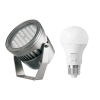
Luminaire Manufacturing Compliance: For LED and fluorescent fixture production under IEC 60598-1/GB 7000.1, the instrument verifies insulation between live parts and accessible metal parts at test voltages derived from (2×V+1000V) formulas, with the 750VA capacity accommodating the capacitive nature of LED driver input filters.
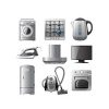
Household Appliance Testing: Under IEC 60335-1 requirements, the system validates basic and supplementary insulation in washing machines, refrigerators, and cooking appliances, with the 100mA AC range supporting high-power heating element testing without current saturation.
Electronic Component Screening: For capacitor, relay, and connector manufacturers, the programmable test duration (1-99s) enables both 100% production screening and extended burn-in testing protocols.
Wire and Cable Quality Control: The DC mode facilitates high-resistance insulation testing of power distribution cables, where the 5kV DC capability verifies XLPE and EPR insulation integrity in medium-voltage cable assemblies.

Selection of appropriate hipot tester capacity requires analysis of the maximum capacitive load anticipated in testing applications. For the WB2671B with 750VA capacity, engineers should verify that reactive power requirements of the DUT do not exceed this threshold. The relationship between test voltage (V), frequency (f), capacitance (C), and reactive power (Q) follows the formula ![]() .
.
For applications involving larger capacitive loads (e.g., power factor correction capacitors or long HV cables), alternative configurations such as the WB2673 series (1-3kVA capacity) may provide necessary power reserves while maintaining the same control interface and safety architecture.
When deploying the WB2671B for regulatory compliance testing, engineers should verify that the instrument’s ±5% accuracy specification meets the specific standard’s measurement uncertainty requirements. For critical applications requiring higher precision, annual calibration against traceable standards is essential to maintain compliance documentation integrity.
The instrument’s compliance with IEC 61010-1 safety requirements for electrical testing equipment should be verified through examination of manufacturer-provided test reports and CE marking documentation, ensuring suitability for deployment in European and international markets.
Dielectric withstand voltage testing remains an indispensable verification procedure for ensuring electrical product safety and regulatory compliance across global markets. The technical complexity of hipot tester systems—encompassing high-voltage generation, precision current measurement, and sophisticated safety interlocks—demands careful engineering evaluation during equipment selection and deployment.
The WB2671B testing system exemplifies the integration of these technical requirements into a practical instrumentation platform, offering 5kV AC/DC capability, extended 100mA current range, and 750VA transformer capacity suitable for diverse manufacturing applications from household appliances to industrial luminaires. Its automated discharge mechanisms and programmable test sequencing address both safety mandates and operational efficiency requirements in modern production environments.
For engineering organizations seeking to establish or upgrade electrical safety testing capabilities, the correlation between theoretical standards (IEC 61010-2-034, IEC 60335-1, GB 7000.1) and the WB2671B’s specification matrix demonstrates a viable pathway to achieving compliance while maintaining testing throughput. Through systematic implementation of the engineering criteria outlined herein, manufacturers can ensure reliable dielectric verification that satisfies evolving international regulatory landscapes.
Tags:WB2671BYour email address will not be published. Required fields are marked *

 中文简体
中文简体