LM-79 Moving Detector Goniophotometer (Mirror Type C)
LSG-6000

High Precision Rotation Luminaire Goniophotometer
LSG-1890B

High Precision Rotation Luminaire Goniospectroradiometer
LSG-1890BCCD

Goniophotometer for Automotive and Signal Lamps
LSG-1950

Goniophotometer for Traffic Signal Lamps
LSG-1950S

Compact Goniophotometer
LSG-1200A

Near Field Moving Detector Goniophotometer
LSG-1900B
Select an organization
to browse standards
What is Digital Oscilloscope?
A digital oscilloscope has the ability to analyze digital data kept in its memory and perform automatic measurements depending on user-specified parameters including voltage deviation, frequency, and rise times. Similarly, it has a variety of ways to present data that has been recorded. This characteristic is explained by the existence of more collected data than what is displayed on the screen.
Additionally, it has the adaptability to provide a wide range of storage, processing, and display options, such as graphics, screenshots that are between a quarter and a half and multi-step processing programs. The use of a digital oscilloscope is appropriate for displaying complicated signal waveforms that necessitate measurements and calculations on particular waveform components to produce numerical and waveform output displays that reflect particular waveform attributes.

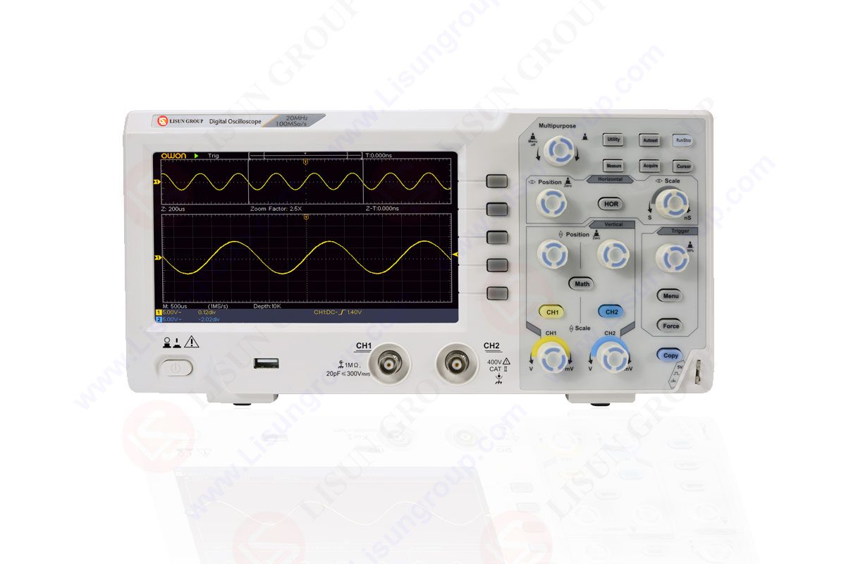
OSP1102 Digital Oscilloscope
Components of a Digital Oscilloscope
A digital oscilloscope consists of six parts. These are amplifiers with analog vertical inputs, a digital waveform memory and an analog-to-digital converter, a Time Base with a Clock Drive and a Trigger, Waveform Displaying and Restructuring Circuits, LCD or LED display and a power supply.
What functions do the buttons of an oscilloscope provide?
The function of opening and shutting is provided by the POWER (On / Off) Button. The brightness of the line on the screen can be changed using intensive. Focus guarantees an adequately narrow line on the screen. The buttons for Vertical-Horizontal Position allow you to adjust the horizontal and vertical positions of the scan lines.
With the help of the Volt button, you may change the input sensitivity from 5 mV/cm to 20 V/cm. It is possible to choose a time between 0.5 m*s/cm and 0.2 s/cm by using the Time / div Button. Hold off regulates the interval between scans. The tilt button has a (+) or (-). Depending on these markers, triggering will either take place in a positive or negative position. Dual Button enables the simultaneous appearance of Channels 1 and 2.
How can you use an Oscilloscope?
The input signal channel of the digital oscilloscope is probed after operation. The two most common measuring probe types are employed. These are the X1 probes, which do not weaken the signal, and the X10 probes, which do so ten times. If a 5 V voltage is present at the probe’s tip when the second type is operating, the voltage enters the oscilloscope as 0.5 V.
This needs to be considered if the sign’s size is to be determined. All modern probes employ BNC type connectors (plugs). The moveable portion on the outside of these plugs is twisted clockwise and locked after they have been placed in their respective slots. This must be taken into account when determining the sign’s size.
What kind of Measurements can be taken with an Oscilloscope?
LISUN digital oscilloscopes allow us to view the values of charge and discharge curves of the capacitor, AC and DC voltage levels; Phase difference; Frequency and Characteristics of semiconductor devices like diodes and transistors. Change electrical magnitude waveforms and the amount of current flowing through the circuit can also be measured. We will look at two types of measurements below.
Voltage Measurement
The vertical axis is used to gauge the signal’s amplitude on the screen. On the screen, squares are used to determine the amplitude initially. The voltage’s real value is then calculated by multiplying the frame rate by the value that the signal on the VOLTS / DIV input attenuator commutator indicates. When using an attenuator-equipped probe (X10 or X100), the attenuation coefficient must also be taken into account. Turning the VOLTS / DIV commutator clockwise increases the oscilloscope’s sensitivity.
Oscilloscope-Based Measurement of Frequency Modern oscilloscopes measure period rather than frequency. On the horizontal axis, period measurements are taken. By counting the squares, one may tell how long one period of the waveform in the X axis direction is. After then, the signal’s period is calculated by multiplying the value shown by the TIMEBASE commutator by the quantity of frames. Time measurements are unaffected by the type of probe (X1, X10, or X100) utilized.
Period or Frequency Measurement
In digital oscilloscopes, period is measured rather than frequency. On the X (horizontal) axis, period measurements are made. By counting the squares, one may tell how long one period of the waveform in the X axis direction is. By multiplying the quantity of frames, we can determine the value of the time / div button. The attenuation coefficient is doubled and taken into consideration, though, if the probe deteriorates.
Axes of a digital Oscilloscope
Vertical axis or Voltage axis
The oscilloscope’s vertical section regulates the tension’s size on the screen. Typically, this part contains two buttons, allowing the user to individually regulate the vertical position and volt/div. The vertical scale on the screen can be adjusted by applying more significant strain on each divider button. The scale is adjusted by rotating the knob both clockwise and counterclockwise.
With a lower size, the waveform is more “zoomed in” on. The vertical repositioning of the waveform on the screen is managed via the Position button. The wave descends when the knob is turned clockwise, and moves to the screen when it is turned counterclockwise. It is possible to remove a portion of a waveform from the screen by using the position button.
Horizontal axis or Time axis
The time scale displayed on the screen is managed by the oscilloscope’s horizontal portion. Position and time / div are the two buttons on the horizontal axis. The amount of seconds that each part is meant to represent will decrease when the time / div button is cranked counterclockwise.
Similar to the vertical system If the time scale is increased by rotating the device counterclockwise, a longer time may be displayed on the screen. The waveform can be moved to the left or right of the screen by adjusting the horizontal offset using the Position button. You can choose how many periods of a waveform you wish to show using the horizontal system. A signal’s many peaks, channels, and removal are all possible.
How do Digital Oscilloscopes compare to the Analog ones?
The stored traces are as bright, as precisely defined, and written as quickly as non-stored traces, which is the main advantage over analog storage. Traces may be kept for an endless amount of time or written to an external data storage device and then loaded again. This enables, for instance, the comparison of a standard trace acquired from a known-good system with a trace acquired from a system that is being tested. There are numerous types that can show the waveform before the trigger signal.
Waveforms are typically analyzed by digital oscilloscopes, which also present numerical values and visual displays. Typical examples of these values are averages, maximum and minimum values, RMS, and frequencies. When utilized in a single sweep mode, they can be used to record transitory signals without the brightness and writing speed restrictions of an analog storage oscilloscope.
After acquisition, the exhibited trace can be altered; for example, a section of the display can be magnified to better show fine detail, or a lengthy trace can be shown in one display to highlight particular regions of interest. The user can annotate a stored trace on many instruments. The flat panel displays used by many digital oscilloscopes are the same ones that are produced in large quantities for computer and television screens. With the use of interfaces like a parallel printer port, RS-232 serial port, IEEE-488 bus, USB port, or Ethernet, digital storage oscilloscopes can be controlled remotely or automatically and can transport captured waveforms to an external display or storage.
Advantages of Digital Oscilloscope
The ability to store digital data for rapid viewing, upload it to a computer, make hard copies of it or store it on floppy disks, and measure instantly on digital data are some of the advantages of the digital oscilloscope over the analog oscilloscope. Digital oscilloscopes may display waveforms immediately after a triggering event, whereas an analog oscilloscope requires triggering before viewing can begin. The best characteristics of digital oscilloscopes are their high storage memory and real-time signal accuracy. Having cutting-edge DSP techniques, they are appropriate for studying high frequency transients.
Oscilloscopes are measuring tools used to examine signal voltages in electrical devices like audio recording and broadcasting equipment for television and radio. Oscilloscopes with digital storage offer the advantage of being able to record and store electronic events that might have taken place when no one was there or when observation was otherwise impossible. Oscilloscopes have a number of benefits over other similar diagnostic equipment, such voltmeters, in addition to this feature.
Graphic Representations
Since they can display signals graphically, digital storage oscilloscopes have an advantage over voltmeters in that they make it easier to visually identify the cause of unexpected voltage. Voltmeters only detect unexpected voltage, which calls for additional diagnostics and troubleshooting. The same voltage may be measured by a digital storage oscilloscope, which will show oscillations in the impacted circuit. Digital storage oscilloscopes’ visual displays of a pulse’s precise form or timing are useful and occasionally required.
Signal Tracing
In order to pinpoint the precise malfunctioning component, professionals might use digital storage oscilloscopes to probe individual connections and parts within electrical devices. The oscilloscope can determine where an expected signal is missing or wrong by monitoring the functions of each individual component. The oscilloscope can assess minute differences in how other components operate and notify the technician to the eventual need for replacement or fine tuning. It may also identify operating parts to prevent mistaken replacement.
Testing New Circuitry
The digital oscilloscope can check for errors in newly developed circuitry, ensuring that it functions properly, or it can spot design flaws like poor voltage levels and electrical noise. Using a dual-trace scope, technicians can check that the internal clock that meters out the actions of other components is running properly by viewing both the clock signal and test signal of the electronic device.
FAQs
What are the general categories of Digital Oscilloscopes?
Single shot digital oscilloscopes and random spaced or comparable time sampling oscilloscopes are the two main forms of digital oscilloscopes. After a trigger condition is satisfied, the single-shot oscilloscope begins real-time sampling of an event. The maximum sampling rate for single shot oscilloscopes is limited by the speed of the analog to digital converter.
The maximum amount of time that may be sampled from a single event depends on the capacity of the buying memory, which receives the device’s output from the converter. By the way, the sampling events that repeat at different sites at specific time intervals are the foundation of the random interspersed oscilloscope or equivalent time sampling oscilloscope.
What is their working principle?
High-speed microprocessors enable digital oscilloscopes to operate on the sampling of the input signal principle. The benefit of this is that the signal may be captured, halted, and triggered at any moment and at any level. The greatest frequency of the signal you can measure with a digital oscilloscope will also depend on the instrument you use, even though analog oscilloscopes have no theoretical upper limit.
Lisun Instruments Limited was found by LISUN GROUP in 2003. LISUN quality system has been strictly certified by ISO9001:2015. As a CIE Membership, LISUN products are designed based on CIE, IEC and other international or national standards. All products passed CE certificate and authenticated by the third party lab.
Our main products are Goniophotometer, Integrating Sphere, Spectroradiometer, Surge Generator, ESD Simulator Guns, EMI Receiver, EMC Test Equipment, Electrical Safety Tester, Environmental Chamber, Temperature Chamber, Climate Chamber, Thermal Chamber, Salt Spray Test, Dust Test Chamber, Waterproof Test, RoHS Test (EDXRF), Glow Wire Test and Needle Flame Test.
Please feel free to contact us if you need any support.
Tech Dep: [email protected] , Cell/WhatsApp:+8615317907381
Sales Dep: [email protected] , Cell/WhatsApp:+8618117273997

 中文简体
中文简体