
LM-79 Moving Detector Goniophotometer (Mirror Type C)
LSG-6000

High Precision Rotation Luminaire Goniophotometer
LSG-1890B

High Precision Rotation Luminaire Goniospectroradiometer
LSG-1890BCCD

Goniophotometer for Automotive and Signal Lamps
LSG-1950

Goniophotometer for Traffic Signal Lamps
LSG-1950S

Compact Goniophotometer
LSG-1200A

Near Field Moving Detector Goniophotometer
LSG-1900B
Select an organization
to browse standards
Goniophotometer definition:
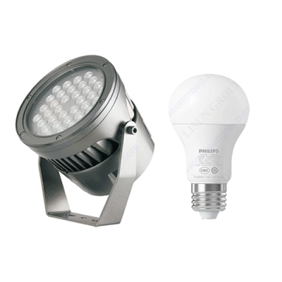
Goniophotometer is used to measure the spatial light intensity distribution and various photometric parameters of LED lamps/street lamps, indoor and outdoor lighting lamps. Including measurement: Luminous Intensity Data, Luminous Intensity Distribution, Zonal Luminous Flux, Luminaries Efficiency,Luminance Distribution,Coefficient Of Utilization, Luminance Limitation Curves Glare, Maximum Ratio of Distance to Height, Equal Illuminance Diagrams, Curves of Luminaires VS Lighting Area, Isocandela Diagrams, Efficient Luminescence Angle, EEI, UGR, etc.

LM-79 Moving Detector Goniophotometer (Mirror Type C)
Operation Steps:
1. Connect the turntable to the controller
Connect the control port on the turntable with the turntable interface on the back panel of the goniophotometer controller with the USB/RS-485 communication line provided by the system, and connect the USB/RS-485 communication line interface of the probe to the USB/RS-485 communication line from the turntable.
2. Connect the turntable to the power supply
Insert one end of the turntable power cord provided with the system into the power socket interface on the panel of the turntable control box, and insert the other end into the turntable power supply interface at the back of the system control cabinet.
3. Fixed probe
According to the darkroom layout, place the probe position, adjust the probe level and pitch position, make the probe face the turntable, and then measure the distance from the light-receiving surface of the probe to the rotation center of the turntable.
4. Installation and electrical connection of lamps
1) Install the lamps and fix them
2) Select the lamp power supply. If it is AC power supply, select the AC terminal, and the AC power supply is input from the “AC INPUT” on the back panel of the turntable; if it is DC power supply, connect the current power supply directly to the terminal on the turntable control box panel. A DC power supply directly supplies power to the lamps.
5. Light up the lamp or lamp under test
6. Software settings before measurement
Turn on the power of the instrument, then open the computer application software, enter the operating menu and select the system type according to the specific model of the product. Click the “System” menu, then click “Connect” under the “System” menu. (After exiting the software normally, there is no need to set it again for the second startup of the software).
7. System check and set communication parameters
In the main interface of the software, click “System Settings” in the “Operation Menu”, and the “System Settings” dialog box will pop up. If the communication between the turntable and the computer is normal, it will display “device online” in the “Turntable Controller” column, otherwise it will display “device offline”; if the photometer and the computer communicate normally, it will display “online” in the photometer column. Otherwise, it displays “offline”. If the column of “Turntable Controller” displays “System Not Connected”, it means that the driver of the communication converter has not been installed or the installation failed, causing the USB device to be unavailable.
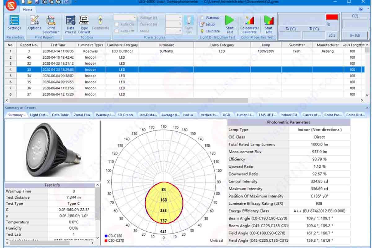
8. Test
1) Click “Reset System” under the “Operation” menu;
2) After waiting for the lamp to be tested to stabilize, select “Light distribution test” under the “Operation” menu, and the test interface will be entered after the system is connected properly.
3) Set the test conditions according to the actual test, such as the angle range, test speed, etc. After setting, press the “Start” button to start the test.
4) After the test is completed, it will prompt to enter the test information. After the input is completed, the test result will be displayed in the main interface after confirming.
9. Save the test results to the corresponding folder.
Lisun Instruments Limited was found by LISUN GROUP in 2003. LISUN quality system has been strictly certified by ISO9001:2015. As a CIE Membership, LISUN products are designed based on CIE, IEC and other international or national standards. All products passed CE certificate and authenticated by the third party lab.
Our main products are Goniophotometer, Surge Generator, EMC Test System, ESD Simulator, EMI Test Receiver, Electrical Safety Tester, Integrating Sphere, Temperature Chamber, Salt Spray Test, Environmental Test Chamber, LED Test Instruments, CFL Test Instruments, Spectroradiometer, Waterproof Test Equipment, Plug and Switch Testing, AC and DC Power Supply.
Please feel free to contact us if you need any support.
Tech Dep: Service@Lisungroup.com, Cell/WhatsApp:+8615317907381
Sales Dep: Sales@Lisungroup.com, Cell/WhatsApp:+8618917996096
LISUN’s indoor and outdoor LED test solutions meet IEC 60598-1, IEC 62722-2-1, CIE 121 standards, covering safety, photometry, and environmental tests for global compliance.

 中文简体
中文简体
