
LM-79 Moving Detector Goniophotometer (Mirror Type C)
LSG-6000

High Precision Rotation Luminaire Goniophotometer
LSG-1890B

High Precision Rotation Luminaire Goniospectroradiometer
LSG-1890BCCD

Goniophotometer for Automotive and Signal Lamps
LSG-1950

Goniophotometer for Traffic Signal Lamps
LSG-1950S

Compact Goniophotometer
LSG-1200A

Near Field Moving Detector Goniophotometer
LSG-1900B
Select an organization
to browse standards
Coupling is the energy exchange linkage between two circuits or two parts in one circuit, enabling energy to be transmitted from one circuit to another or from one part to another. Decoupling is the prevention of energy feedback from one circuit to another, to avoid unpredictable feedback reactions, resulting in abnormal operation of the next level amplifier or other circuits.
By separating noise from the circuit with the coupling-decoupling network, the signal can be made cleaner and more stable. The coupling-decoupling network is composed of two capacitors and one inductor. The two capacitors are responsible for separating the high-frequency signal from the direct current signal, and the signal is separated through the inductor. When the high-frequency signal passes through the inductor, the bias voltage will change, thus changing the amplitude of the voltage on this basis. In short, the high-frequency noise is separated from the direct current signal. Through coupling and decoupling networks, the influence of high-frequency noise disturbing the transmission of circuit signal can be effectively blocked.
Its advantages are ease of use, small size, and good performance. By adding a capacitor to the signal line of the circuit, the capacitor can bypass the high-frequency noise signal to the ground line, and a capacitor is used to isolate the DC signal, thereby realizing the transmission of the signal. In short, the coupling and decoupling networks technique separates the DC signal from the high-frequency signal in order to remove noise interference. Capacitors can be used to divide the DC signal from the high-frequency signal, and the inductor can separate the high-frequency signal from the DC signal, thus achieving the effect of eliminating noise interference.
The inductor is used in the coupling-decoupling network to separate the high-frequency noise signal from the direct current signal. It has high impedance characteristics to high-frequency signals, which allows it to separate the high-frequency noise signals, while the direct current signals can pass through it smoothly to the next circuit. By adding the inductor to the coupling and decoupling networks, the high-frequency noise signals can be effectively separated from the direct current signals, thereby ensuring that the direct current signals are transmitted cleanly.
The main function of the coupling network is to transmit the surge signal of the synthesized wave generator (such as the surge generator) to the test unit (EUT) without damaging the protection generator itself, reducing the impact on the surge waveform. The decoupling network provides sufficient decoupling impedance for the surge signal to prevent the surge from entering the power grid and affecting the normal operation of non-test devices.

CDNE-M316_Coupling Decoupling Network
Using the coupling-decoupling network can effectively transmit the surge signal from the synthesized wave generator to the circuit of the test device, preventing the synthesized wave generator from being damaged, and reducing the influence on the surge waveform. At the same time, decoupling network can provide good decoupling impedance effect, effectively preventing the surge from entering the circuit and causing a negative effect on other devices, such as surge arresters. Therefore, by using the coupling and decoupling networks, good surge immunity can be achieved.
There are many ways to realize the coupling network, such as capacitive coupling and gas discharge tube coupling, but since the gas discharge tube coupling significantly affects the output waveform of the synthesized wave generator, capacitive coupling is more common. In view of the relationship between output signal efficiency and residual voltage, the national standard stipulates that 18 μF capacitance is used for line-line coupling (differential mode) and 9 μF capacitance is used for line-ground coupling (common mode). When line-ground coupling, in order to ensure the virtual impedance (defined as the ratio of open circuit voltage peak-to-peak and short circuit current peak-to-peak), an additional resistance of 10Ω should be serially connected to increase the effective source impedance.
The decoupling network consists of an LC low-pass filter (decoupling inductor L and decoupling capacitor C) which can effectively stabilize the voltage at the EUT side. The equivalent circuits of line-ground and line-line decoupling networks are: Rs and R′s are the source resistances of the surge source, Rs=12Ω, s=2Ω respectively, making the voltage transmission function properly changed, so as to more effectively stabilize the voltage at the EUT side.
Tags:CDNE-M316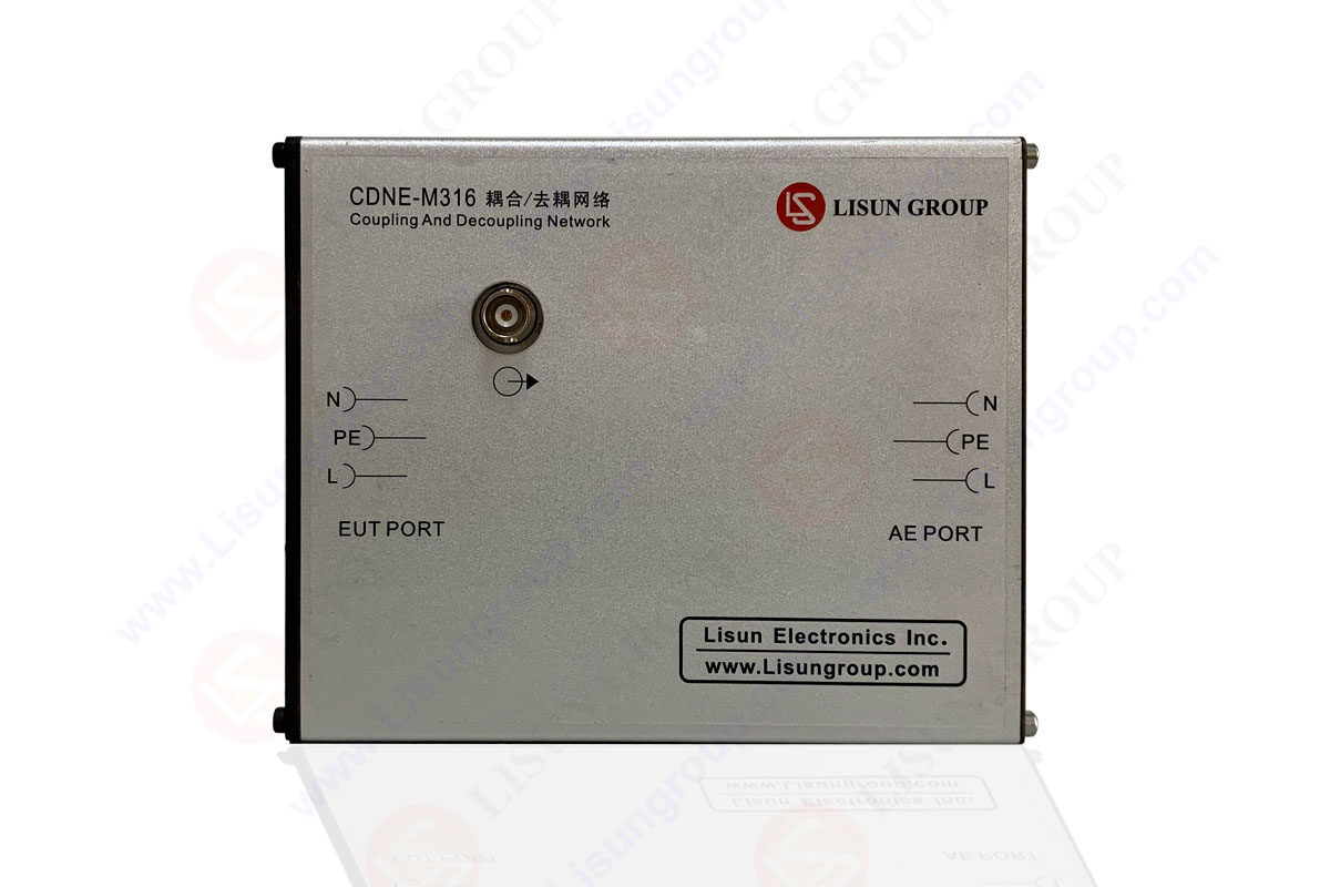

 中文简体
中文简体