
LM-79 Moving Detector Goniophotometer (Mirror Type C)
LSG-6000

High Precision Rotation Luminaire Goniophotometer
LSG-1890B

High Precision Rotation Luminaire Goniospectroradiometer
LSG-1890BCCD

Goniophotometer for Automotive and Signal Lamps
LSG-1950

Goniophotometer for Traffic Signal Lamps
LSG-1950S

Compact Goniophotometer
LSG-1200A

Near Field Moving Detector Goniophotometer
LSG-1900B
Select an organization
to browse standards
Abstract
The oscilloscope stands as one of the most fundamental and indispensable instruments in electrical engineering, serving the essential function of converting invisible electrical signals into visible waveform displays. This article provides a comprehensive answer to the question “what does an oscilloscope measure,” exploring the core principle of capturing voltage variations over time and detailing the key electrical parameters that can be quantified. We examine the technical architecture of modern digital oscilloscopes and use the LISUN OSP1102 digital oscilloscope as a practical example to illustrate how specifications such as bandwidth, sampling rate, and vertical resolution enable precise measurements. This guide offers engineers, technicians, and electronics enthusiasts a clear framework for understanding how oscilloscopes have become essential tools for circuit debugging, signal analysis, and equipment validation.
1. Introduction: The “Eyes” of the Electronics World
During the design, debugging, and repair of electronic systems, engineers must observe whether electrical signals at various circuit nodes are behaving as expected. A multimeter can only provide single numerical readings of voltage or frequency—it cannot reveal the true nature of a signal. So what does an oscilloscope measure? The fundamental answer is this: it measures and displays the complete waveform of signal voltage as it changes over time. In essence, an oscilloscope gives engineers the ability to “see” how electrons flow through a circuit.
Whether you’re verifying that a clock signal runs at the correct frequency, troubleshooting interference on a digital communication line, or measuring the transient response of a power supply switch, the visual waveform provided by an oscilloscope serves as the definitive basis for analysis and decision-making.

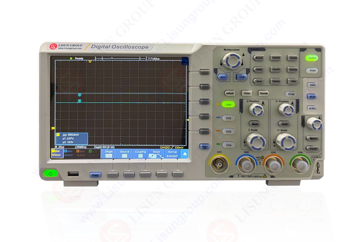
OSP1102
2. Core Measurement Parameters of an Oscilloscope
An oscilloscope does far more than simply display waveform shapes—it enables precise quantitative analysis. To fully understand what does an oscilloscope measure, one must recognize the key electrical parameters it can capture either directly or through calculation.
• Voltage Parameters represent the oscilloscope’s primary direct measurements. These include peak voltage, peak-to-peak voltage, average value, and RMS (root mean square) value. Using cursors or automatic measurement functions, users can easily read the instantaneous voltage at any point on the waveform.
• Time-Domain Parameters are derived from the horizontal time axis. These include period, frequency, rise time, fall time, pulse width, and duty cycle. Such parameters are critical for digital circuit timing analysis and signal integrity verification.
• Derived Parameters are calculated from voltage and time measurements. Examples include phase difference (requiring two or more channels) and integral/derivative values (useful for analyzing energy or rate of change).
Modern digital oscilloscopes typically include dozens of built-in automatic measurement functions, enabling one-touch statistical analysis and display of these parameters—dramatically improving measurement efficiency.
3. Technical Implementation of Modern Digital Oscilloscopes
Unlike traditional analog oscilloscopes, modern digital storage oscilloscopes employ analog-to-digital conversion technology to transform continuous analog signals into discrete digital samples for processing and display. This process depends on several key technical specifications that define measurement capability.
• Bandwidth refers to the highest frequency of a sinusoidal signal that the oscilloscope can accurately measure. Insufficient bandwidth causes high-frequency signal components to attenuate, resulting in waveform distortion. As a general rule, measurement bandwidth should be at least three to five times the highest frequency component in the signal of interest.
• Sampling Rate indicates how many times per second the oscilloscope samples the input signal, expressed in samples per second (Sa/s), such as 1 GSa/s. According to the Nyquist sampling theorem, the sampling rate must be at least twice the signal’s highest frequency to reconstruct the waveform. In practice, a sampling rate of four times or higher is recommended to avoid aliasing.
• Vertical Resolution refers to the bit depth of the analog-to-digital converter, which determines how finely the oscilloscope can quantize input voltage into digital values. A common 8-bit resolution provides 256 quantization levels, while 14-bit resolution offers significantly finer voltage detail.
• Memory Depth indicates the number of waveform points the oscilloscope can capture and store in a single acquisition. Deep memory allows capture of longer time windows at high sampling rates, which is essential for analyzing complex signal sequences or intermittent faults.

4. LISUN OSP1102 Digital Oscilloscope: A Performance Analysis
The LISUN OSP series of digital oscilloscopes is designed to meet general-purpose electronic testing requirements with high-precision instrumentation. Taking the OSP1102 model as an example, its specifications clearly define its measurement capabilities.
• 100 MHz Bandwidth and 1 GSa/s Real-Time Sampling Rate: This combination ensures stable, distortion-free capture and display of common digital and analog signals up to tens of MHz—meeting the debugging needs of most consumer electronics, power supply, and motor control applications.
• Dual-Channel Input: Allows simultaneous observation of two related signals, facilitating timing comparisons, phase analysis, or trigger coupling.
• 8-Bit Vertical Resolution and 7-Inch Display: Provides clear, sufficiently detailed waveform visualization for examining signal characteristics.
The OSP series comparison table below shows that the OSP1102 is positioned for entry-level to mid-range general-purpose measurement applications. For applications requiring higher bandwidth (such as 200 MHz or 300 MHz), more channels (4 channels), or higher vertical resolution (14-bit) to observe finer signal details, users can select other models within the OSP series.
Table 1: Key Specification Comparison of LISUN OSP Series Digital Oscilloscopes
| Model | Channels | Bandwidth | Real-Time Sampling Rate | Vertical Resolution | Screen Size | Typical Application |
|---|---|---|---|---|---|---|
| OSP1102 | 2 | 100 MHz | 1 GSa/s | 8 bits | 7 inches | General electronics repair, education, basic R&D |
| OSP3202E | 2 | 200 MHz | 1 GSa/s | 8 bits | 8 inches | High-speed digital circuits, switch-mode power supply debugging |
| OSP3302 | 2 | 300 MHz | 2.5 GSa/s | 8 bits | 8 inches | Higher-speed digital signals, communication interface analysis |
| OSP3202A | 2 | 200 MHz | 2.5 GSa/s | 14 bits | 8 inches | High-precision analog signals, sensor signal measurement |
| OSP3104E | 4 | 100 MHz | 1 GSa/s | 8 bits | 8 inches | Multi-channel correlated signal analysis (e.g., three-phase drives) |
| OSP3104AE | 4 | 100 MHz | 1 GSa/s | 14 bits | 8 inches | Multi-channel high-precision measurement |
| OSP3104ET* | 4 | 100 MHz | 1 GSa/s | 8 bits | 8 inches | Switch life testing and I²t calibration |
5. Core Application Scenarios for Oscilloscopes
The true value of understanding what does an oscilloscope measure lies in its ability to solve real-world engineering problems across a wide range of applications.
• Digital Circuit Debugging: Measure timing and voltage levels of clock signals, data buses, and PWM outputs from microcontrollers and FPGAs. Identify glitches, race conditions, and other timing anomalies.
• Analog Circuit Analysis: Observe input/output waveforms of amplifiers, frequency response of filters, and startup behavior of oscillators. Measure signal distortion and noise amplitude.
• Power Supply Testing: Measure switching transistor Vds waveforms, output ripple and noise, and power-on/power-off sequencing to evaluate power quality and stability.
• Embedded Systems and Communications: Decode low-speed serial bus protocols such as I2C, SPI, UART, and CAN to verify communication data integrity (supported on select advanced models).
• Education and Research: Serve as a fundamental instrument for validating circuit theory, observing component characteristics, and completing coursework experiments and prototype testing.
Table 2: Core Oscilloscope Applications and Corresponding Measurement Parameters
| Application Area | Typical Measurement Task | Key Oscilloscope Parameters |
|---|---|---|
| Power Circuits | Switching ripple measurement | Peak-to-peak voltage (ripple magnitude), frequency |
| Switching device stress analysis | Peak voltage, rise/fall time, pulse width | |
| Digital Systems | Clock signal quality | Frequency/period, rise time, overshoot/undershoot voltage |
| Digital protocol verification | Pulse width, timing intervals, logic level voltage | |
| Analog/RF Circuits | Amplifier output observation | Peak-to-peak voltage/RMS, waveform distortion |
| Sensor signal acquisition | Instantaneous voltage, signal trend | |
| General Troubleshooting | Signal presence/shape | Waveform display, peak voltage |
6. Conclusion
In summary, answering the question “what does an oscilloscope measure” means understanding how this instrument transforms abstract electrical quantities into information that can be visually perceived and mathematically quantified. At its core, an oscilloscope measures the functional relationship between voltage and time, enabling comprehensive diagnosis of electronic system health and performance.
Selecting an appropriate oscilloscope, such as the LISUN OSP1102, means equipping your engineering workflow with a reliable and accurate observation platform. Specifications like bandwidth and sampling rate define the boundaries of measurement capability, while intelligent features such as automatic measurements and waveform storage significantly enhance productivity. In today’s rapidly evolving electronics landscape, the oscilloscope’s foundational role remains unchanged. It continues to serve as the most direct and reliable bridge between circuit design theory and the physical world—an essential tool that every electronics professional must master and utilize effectively.

 中文简体
中文简体