
Product No: GTS-LS
GTS-LS imaging luminance meter glare test system adopts high-precision imaging luminance meter. Through precise electronically controlled pan/tilt and dedicated measurement and control software, it realizes high-precision measurement and analysis of unified glare value URG, glare index TI, glare value GR of stadiums, uncomfortable glare DGI of windows, brightness, brightness uniformity, maximum value, minimum value, average value, brightness distribution curve, and brightness pseudo-color, meeting the requirements of CIE 115, GB/T 5700-2023, GB/T 50034-2024, JGJ/T 163-2008, JGJ/T 153-2007, CJJ 45-2015 and other standards.
Product features:
• High-precision measurement: The color filter strictly matches the human visual function V(λ), which can accurately obtain true and accurate brightness data;
• Rich software functions: It has single-point, multi-point, and regional brightness and chromaticity uniformity distribution pseudo-color diagrams and other functions, and each parameter can set upper and lower limits;
• Exposure area: The exposure area of any pixel size can be set;
• Support secondary calibration function;
• Rich interfaces: Equipped with input and output IO interfaces, it can be triggered and tested with the customer’s PLC and other automation equipment, and output qualified or unqualified (PASS/NG) indications. SDK software packages developed by third parties can also be provided.
Specification:
| Parameter Name | Specifications |
| Optics | 4/3″ |
| Sensor Model | COMS |
| Camera Type | Y Camera |
| Pixel size | 3.45*3.45um |
| Effective pixels | 16 million |
| Exposure method | Frame Exposure |
| Resolution@Framerate | 4112*4112 Max@23.5fps |
| Signal-to-Noise Ratio | 40dB |
| Dynamic Range | 73.6dB |
| Sensitivity | 1 146mV |
| AD Width | 12bit |
| Output pixel width | 12bit |
| Acquisition Mode | Continuous/soft trigger/hardware trigger |
| Maximum gain (multiple) | 250 |
| Exposure area | Can set any pixel size for movement |
| Exposure time range (ms) | 0.0141~29546.9 |
| Frame Buffer | 128MB |
| Lens mount | Optional CSC port |
| Data Interface | USB3.0 |
| Power Supply | 5V |
| Power | <2W |
| Dimensions | 155*131*126mm |
| Weight | 500g |
| Measuring Range | 0.01~10,0000cd/m² |
| Measurement Accuracy | Class A (±4% reading ±1 reading) under A light source |
| Measurement Repeatability | ±0.1% |
| Lens Focal Length | 12mm |
| Sensor Type | Color filter matching of human visual function V(λ) |
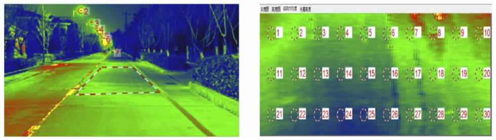
Region Transformation
Measuring road glare requires assessing the longitudinal uniformity, overall uniformity, and average luminance of the road surface. According to the IEC 60050-841: 2014 (GB 5700) standard, the measurement points on the road surface must be evenly distributed. When using a glare luminance meter for road imaging, the road surface appears as a trapezoidal region in the luminance image. To address this, the software provides a quadrilateral-to-rectangle transformation algorithm for luminance uniformity analysis.
Region Transformation
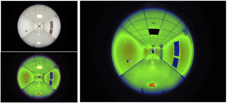
Automatic identification and classification of light sources
Glare evaluation requires information on the spatial position, solid angle, average luminance, and illuminance of each light source. Therefore, the glare luminance meter features a luminance threshold-based light source identification algorithm, which can detect, label, and classify each light source. Based on glare calculation standards, the algorithm determines whether each light source should be included in the glare measurement results.
Automatic identification and classification of light sources
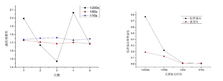
Flickering light source correction
In China, the power supply frequency for electric light sources is 50-60Hz, resulting in a flicker period of approximately 10Hz. For glare measurements, the exposure time for luminance measurement is typically set at 1/1000s, which is much shorter than the flicker period of the light source. This fluctuation in light output significantly affects the repeatability of glare measurement results. Our provided flicker light source measurement mode effectively mitigates the impact of light source flicker on measurement results.
Flickering light source correction
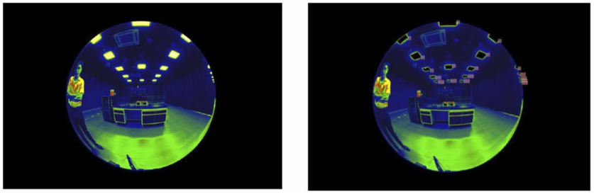
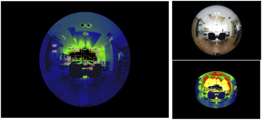
Field of view correction
Indoor UGR (Unified Glare Rating) and DGI (Daylight Glare Index) measurements both use a fisheye lens with a 180° field of view. However, the human eye’s observation field of view is 143° horizontally and 124° vertically. Therefore, glare analysis needs to be adjusted according to the human eye’s observation range. Konia Optoelectronics provides a field-of-view correction function tailored for human eye observation.
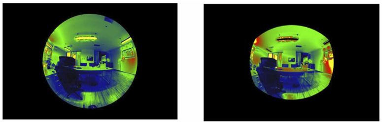
Field of view correction
Customize light source analysis area
When optimizing the design of lighting scenarios, it is essential to understand the contribution of each luminaire or light source at specific locations to glare. This information is used to adjust and optimize the installation position and angle of the luminaires. Konia Optoelectronics offers a manual selection feature that allows users to delineate specific light source areas and provides the glare contribution of the selected region independently.
Customize light source analysis area
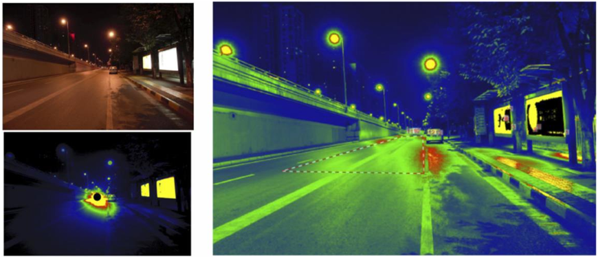
Application1:Road lighting
Measurement parameters: average road surface brightness, longitudinal uniformity, overall uniformity, threshold increment TI
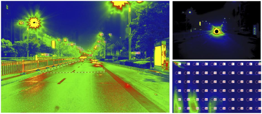
Road lighting
Application 2: Tunnel lighting
Measurement parameters: outside brightness L20, inside wall brightness, road brightness, threshold increment TI
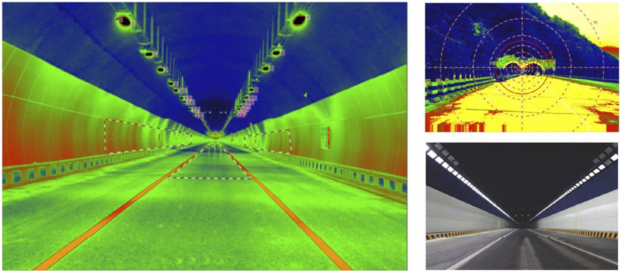
Tunnel lighting
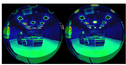
Application 3: Interior lighting
Measurement parameters: Unified Glare Index UGR
Interior lighting
Application 4: Stadium lighting
Measurement parameters: Glare index GR
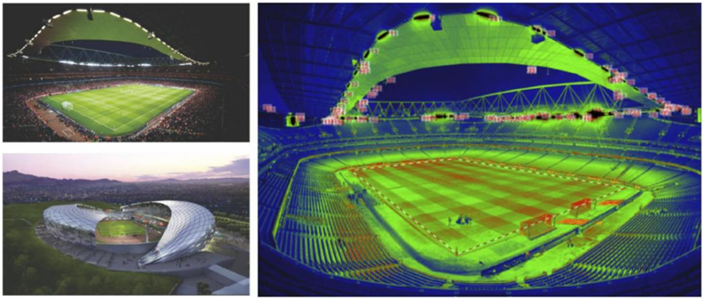
Stadium lighting
Application 5: Building lighting
Measurement parameters: glare index DGI
Building lighting
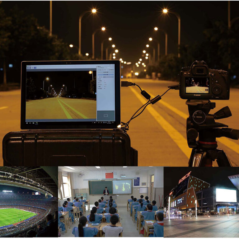
Application 6: Vehicle-mounted road lighting analysis system
Measurement parameters: illumination, brightness, chromaticity, threshold increment TI
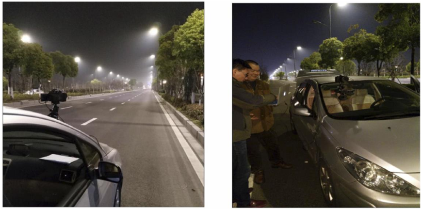
Vehicle-mounted road lighting analysis system
Application 7: Road Interference Light Analysis
Measurement parameters: vertical illumination, brightness, luminous intensity, threshold increment TI
Road Interference Light Analysis
Application 8: Landscape Lighting
Measurement parameters: vertical illumination, brightness, luminous intensity, glare index GR
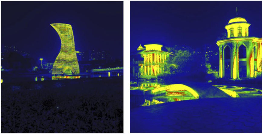
Landscape Lighting

 中文简体
中文简体