
LM-79 Moving Detector Goniophotometer (Mirror Type C)
LSG-6000

High Precision Rotation Luminaire Goniophotometer
LSG-1890B

High Precision Rotation Luminaire Goniospectroradiometer
LSG-1890BCCD

Goniophotometer for Automotive and Signal Lamps
LSG-1950

Goniophotometer for Traffic Signal Lamps
LSG-1950S

Compact Goniophotometer
LSG-1200A

Near Field Moving Detector Goniophotometer
LSG-1900B
Select an organization
to browse standards

Product No: GNGPL-3617
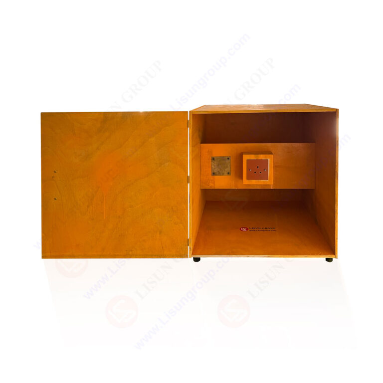
This BS1363-1 Figure 17a Test Cabinet and BS1363-1 17b Dummy Front Plate for Temperature Rise, specifically engineered in strict compliance with BS 1363-1 Figure 17a and Figure 17b standards. It is designed to conduct accurate temperature rise tests for 13 A plugs, socket-outlets, adaptors, and connection units, providing reliable and consistent test conditions that meet international electrical product certification requirements. The integrated design ensures ease of operation while maintaining the precision needed for professional electrical performance testing.
Specifications
• Test standard compliance: BS 1363-1 (Figure 17a for test cabinet, Figure 17b for dummy front plate)
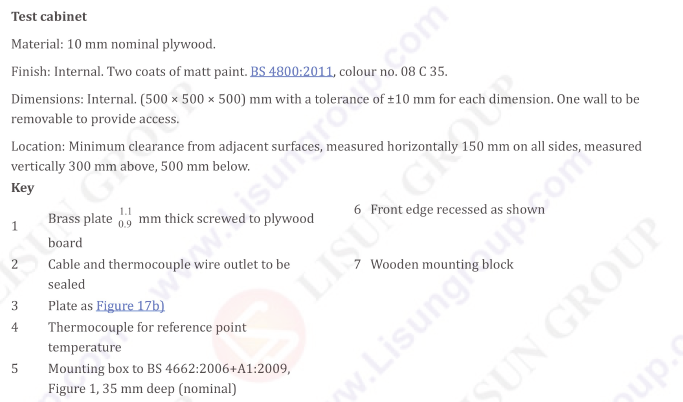
• Test cabinet material: 10 mm nominal plywood with internal finish of two coats of matt paint (BS 4800:2011, colour no. 08 C 35)
• Test cabinet internal dimensions: 500 × 500 × 500 mm (tolerance of ±10 mm for each dimension)
• Installation clearance requirements: Minimum 150 mm horizontal clearance from adjacent surfaces; 300 mm vertical clearance above and 500 mm below
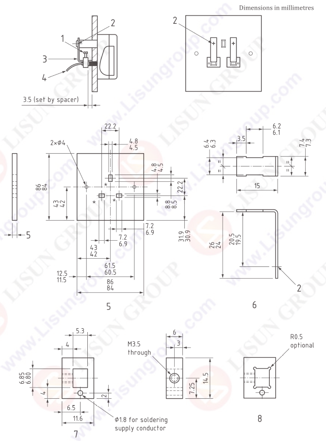
• Dummy front plate components: 0.1 mm thick brass plate screwed to plywood board, with front edge recessed as specified
• Cable and thermocouple wire outlet: Configured to facilitate wiring and temperature sensing
• Wooden mounting block: Included for stable installation of test samples
• Conductive features: Supply conductor interface and ϕ1.8 holes for soldering (as per standard specifications)
• Fastening details: M3.5 screws with R0.5 radius (optional through-hole design)
Test Procedures
• Prepare the test environment by ensuring the test cabinet meets the required clearance specifications (150 mm horizontal, 300 mm above, 500 mm below) and is placed on a stable surface.
• Install the dummy front plate onto the test cabinet using the provided wooden mounting block and fastening components, ensuring a secure and aligned fit.
• Mount the 13 A plug, socket-outlet, adaptor, or connection unit to be tested onto the dummy front plate according to the standard’s positioning requirements.
• Connect the supply conductor to the test sample and route thermocouple wires through the designated outlet for temperature monitoring, ensuring proper contact with key test points.
• Verify that all components are securely fixed and wired correctly, with no loose connections or misalignments that could affect test results.
• Initiate the temperature rise test in accordance with BS 1363-1 protocols, maintaining the specified test conditions throughout the duration.
• Record temperature data continuously via the thermocouple system to assess the sample’s thermal performance against the standard’s requirements.
• Conclude the test once the specified duration is completed, and disconnect the power supply before removing the sample for result analysis.
Applications
• Temperature rise testing of rewirable and non-rewirable 13 A fused plugs compliant with BS 1363-1 standards.
• Performance evaluation of 13 A socket-outlets, adaptors, and connection units to ensure thermal safety during operation.
• Quality control and compliance testing in manufacturing facilities producing electrical accessories for markets adhering to BS 1363-1 specifications.
• Certification testing conducted by third-party laboratories and regulatory bodies to validate product conformity.
• R&D testing for optimizing the thermal design of 13 A plugs and related electrical components.
• Pre-shipment inspection for exporters ensuring products meet the thermal safety requirements of target markets.
BS1363-1 Figure 17a Test Cabinet
BS1363-1 17b Dummy Front Plate for Temperature Rise

 中文简体
中文简体