LM-79 Moving Detector Goniophotometer (Mirror Type C)
LSG-6000

High Precision Rotation Luminaire Goniophotometer
LSG-1890B

High Precision Rotation Luminaire Goniospectroradiometer
LSG-1890BCCD

Goniophotometer for Automotive and Signal Lamps
LSG-1950

Goniophotometer for Traffic Signal Lamps
LSG-1950S

VAD Fire Alarm Visual Alert Device Goniophotometer
LSG-1930

Compact Goniophotometer
LSG-1200A

LED Goniophotometer
LSG-1100
 LEDs and Luminaire Test Solutions
 LM-79 and LM-80 Test Solutions
 LED Driver Test Solutions
 Household Appliances Test Solutions
 Mobile and Network Test Solutions
 Automotive Electronics Test Solutions
 Audio-Video and IT Test Solutions
 Cable and Wire Test Solutions
 Plugs and Sockets Test Solutions
 Power Switch Test Solutions
 Transformer Test Solutions
 Electric Toys Test Solutions
 Energy Meter Test Solutions
 Motor-Operated Tool Test Solutions
Select an organization
to browse standards
Working Principle of Surge Generator SG 61000-5
The SG 61000-5 standard is based on immunity criteria. It defines the test techniques as well as the standard testing levels for equipment against unidirectional surges caused by switching and lightning transients. The degrees of electrical and electronic equipment testing vary depending on the environment and installation conditions. Establishing a single reference for calculating the surge resistance of electrical and electronic equipment is the main goal of this standard.
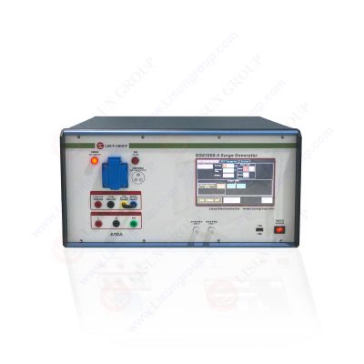
SG61000-5_Surge Generator
The immunity stress of Surge Protection SG 61000-5 is characterized as being indicative of voltage and current pulses. These pulses are generated on the power networks which result in events that occurred outside of the device under test. Surges are typically caused by power system switching transients such as capacitor bank switching or load shifts. Lightning causes surges on power lines, either directly on the transmission line or because of a nearby lightning strike.
Capacitor-Discharge Technique
A surge generator is used to carry out the capacitor discharge procedure. This apparatus is used to convert electricity lines into high voltage, unidirectional impulses. The impulses are then transmitted via the defective power connection. The voltage of the power supply has a direct relationship with capacitor charges. As we close the switch, the capacitor discharges a high voltage impulse into the cable under test.
Finally, we examine the findings. The curve depicts how time affects voltage when a gap flashes over. The curve is created by applying increasing voltages to the gap and measuring the time lag until the sparks stop. The curve will show shorter time delays before the flashover and a higher applied voltage. There is frequently a small temporal lag, below which the gap will never flashover. Below a certain voltage, shown by the “Minimum Break-down voltage,” a gap will never flashover within a usual test time of several minutes.
Surge Immunity Tests
Qualification Exam Surge tests the DUT’s resistance to very high voltage levels over a short period of time (such as a lightning strike). External standards demand surge peak voltage (SG 61000-5 and IEC 61000-5). A sample test is the surge test. It employs a common surge waveform. The surge waveform rises in 1.2 microseconds and falls in 50 microseconds.
Each unit is stressed with 50 consecutive surge pulses before failing or passing. RIO is used to check these results after the surge. The resistance from the left to the right side at 500 volts is measured as RIO. When tested for 60 seconds at 5.7 kV RMS isolation, the leakage should be less than 30 microamps. Other methods for statistical analysis of surge characterization data are available. The surge immunity test simulates low-frequency power surges.
Here are a few instances where you could anticipate seeing surge incidents.
• Power switching occurrences
• Insulation failures in the Power grid
• Switching reactive loads nearby (e.g., motors)
• Fuses are blowing (flyback voltage)
• Lightning strikes in the vicinity (indirectly)
Surge Coupling Methods
EMC surge testing
Surge is often provided to AC (or DC) power input ports, although certain standards require it to be applied to signal ports as well.
Surge pulses are often linked to the signals directly via a properly determined source impedance (e.g., 2 and 18uF in series).
The coupling network is typically housed within an immunity test system, together with a decoupling network that aids in the protection of the power supply or auxiliary equipment.
Some typical failure modes in surge testing
Surge testing requires a significant amount of energy. For a short amount of time, the currents involved can easily approach 100A. It is quite easy to ruin your product with this much energy.
Some commonly faced issues are given as follows:
• ICs frying.
• Cabling deterioration.
• Thermal problems.
• Arcing seems to be quite common.
• Motor windings are damaged.
For lightning simulation testing, lightning surge generators are utilized. Many test standards demand indirect lightning tests on components that will be placed in the commercial avionics, automotive, and military industries. To achieve immunity test standards, these tests must be done on components, products, devices, and vehicles. Single stroke and multiple stroke lightning surge simulators are required by RTCA/DO-160 Section 22 and MIL-STD-461.
Lightning Surge Generator Tests
MIL-STD-461G is mentioned in five test applications.
Multiple Stroke -Waveforms 1 and 2. Compatible with all aircraft
Waveform 3 – Multiple Stroke (apply at both 1 and 10 MHz) All planes are affected.
Waveforms 4 and 5 apply to airplanes with composite skin/structure. An all-metal skin/structure aero plane is not eligible.
Waveform three, Multiple Burst (apply at both 1 and 10 MHz).
Multiple Burst -Waveform 6. Only for low impedance bundles.
FAQs
What causes impulse voltage?
Lightning impulses and system switching impulses are the primary causes of these voltage surges in the electrical grid. However, other factors, such as resonance, arcing on the ground, and insulation failure, may also contribute to power system overvoltage.
What is the purpose of an impulse generator?
The purpose of impulse voltage generators is to produce impulse voltages that mimic switching surges and lightning strikes. A charging rectifier, “Marx Circuit” impulse stages, an impulse voltage divider, and an impulse voltage measurement system make up the entire test system.
How do you measure surge voltage?
A charged capacitor is swiftly switched in parallel during surge voltage testing, also known as a surge test, to produce a surge pulse in the windings that must be examined. After connection, the capacitor’s stored energy is released into the inductivity, then returned to the capacitor, and so forth. For coils and motors with random and form wounds: Test voltage is V = 2E+1000V, where E is the motor’s RMS rated Line to Line voltage. For windings, stators, complete motors, and all types of generators, this is the most popular test voltage formula.
Lisun Instruments Limited was found by LISUN GROUP in 2003. LISUN quality system has been strictly certified by ISO9001:2015. As a CIE Membership, LISUN products are designed based on CIE, IEC and other international or national standards. All products passed CE certificate and authenticated by the third party lab.
Our main products are Goniophotometer, Integrating Sphere, Spectroradiometer, Surge Generator, ESD Simulator Guns, EMI Receiver, EMC Test Equipment, Electrical Safety Tester, Environmental Chamber, Temperature Chamber, Climate Chamber, Thermal Chamber, Salt Spray Test, Dust Test Chamber, Waterproof Test, RoHS Test (EDXRF), Glow Wire Test and Needle Flame Test.
Please feel free to contact us if you need any support.
Tech Dep: Service@Lisungroup.com , Cell/WhatsApp:+8615317907381
Sales Dep: Sales@Lisungroup.com , Cell/WhatsApp:+8618117273997
Your email address will not be published. Required fields are marked *

 English
 中文简体
中文简体 English
 Русский
 Español
 Português
 Türkçe
 العربية
 Deutsch
 Polski
 Italiano
 Français
 한국어
한국어 ไทย
ไทย Tiếng Việt
 日本語
日本語