LM-79 Moving Detector Goniophotometer (Mirror Type C)
LSG-6000

High Precision Rotation Luminaire Goniophotometer
LSG-1890B

High Precision Rotation Luminaire Goniospectroradiometer
LSG-1890BCCD

Goniophotometer for Automotive and Signal Lamps
LSG-1950

Goniophotometer for Traffic Signal Lamps
LSG-1950S

Compact Goniophotometer
LSG-1200A

Near Field Moving Detector Goniophotometer
LSG-1900B
Select an organization
to browse standards
In the field of product development, electromagnetic compatibility (EMC) research has become increasingly important. Many engineering departments hope to have their own EMC testing environment. In the EMC test, the radiation launch measurement of the product is particularly important for the test environment and equipment. The environment for radiation launch requirements is an open field (OATS) or a semi -electrocular room (SAC). For other forms of EMC tests, there is enough workbench or shielding room; the implementation of the radiation resistance test index is used, the full wave dark chamber is used.
This article mainly discusses some venue design problems about radiation launch testing. The open field is a preferred test venue. However, due to the increasingly serious electromagnetic “pollution” and the dependence of the climate on the climate, the semi -wave dark room has become a substitute for economics. This article combines civil EMC test standards to introduce some introductions to the design and construction problems for radiation launch test SAC.
1. The shielding room SAC is composed of a shielding room equipped with a suction material. The shielding room isolates the internal capacitance and the external electromagnetic environment. Environmental electromagnetic wave spectrum comes from including TV signals, radio radio, personal communication equipment, and human environmental noise. The role of the shielding room is to make the external harassment intensity inside the shielding room significantly lower than the interference field strongly produced by the test device (EUT) itself.

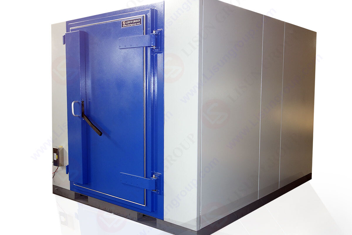
SDR-2000B_Magnetic Shielding Cabinet for EMI Testing
In the construction of the shielding room of SAC, there are two basic structures: combined and welded. The combination type consists of a fixture connected to the wall plate and the wall plate. The wall plate can be a plywood on both sides or a galvanized steel plate covered with a galvanized thin layer. The fixture makes the wall plate installation into a whole and ensures the conductive continuity of the wall plate. At the same time, pads and high -frequency wave suction materials are often used to improve shielding performance. Even though most manufacturers apply the same shielding system concept, due to the differences in the respective characteristics of the equipment, the performance of each product in the market is inconsistent. The welding structure is a tightly sealed sealing body for the welding of the steel plate or copper plate through the welding. This is a technology that requires precise technology. The high -level welding body makes the shielding effect stable and reliable, and at the same time, the high -performance shielding performance depends on the exclusion of the weld vulnerability. Of course, the unsatisfactory factor of the welding structure is higher cost.
For electromagnetic compatibility tests in SAC, flooring is an important part. In the radiation launch test, a part of the emission signal of EUT is reflected through the floor, which is received and received by receiving antenna measurement, just like the actual situation in the office. Simulate a good floor to make the floor have conductive continuity, and the surface fluctuation changes should be as small as possible. We can achieve this effect by building an elevated floor. The so -called elevated floor is an overhead floor made of the same metal material as the wall and ceiling. The mechanical parts of the measuring and controlled cables, power cords, and turntables are placed under the elevated floor. The elevated floor is generally height from 30cm to 60 cm according to the situation of the transfer mechanical part. In order to enable the floor to obtain a complete conductive continuous, the conductive surface and the surrounding floor on the platform are ensured that the conductive is continuous. It is usually implemented by the method of grounding circular space connection.
For the purpose of the operation, the perforation of the shielding room is required. The perforation needs to be carefully selected, and the integrity of the shielding room should be maintained during construction. A typical SAC includes the basic perforation of several types introduced below.
1.1 Channel door is obvious, at least one door. The most common part is a groove contact device, that is, a single -knife and double spring, a single -knife structure by the door, and the groove structure of the door frame. Make sure the conductive continuity. The more popular and low price is the rotary door, which has one or two union. The rotating door can be installed on one or two units, but the static space after opening the door is very small. To make up for this, sliding doors are also a choice. It has the advantage of convenient use and suitable price.
1.2 For the purpose of air flow and refrigeration, the waveguide windows are lower than the cut -off frequency. The operating frequency of most wave -conducting windows can reach 10GHz. For higher frequencies, such as 40GHz, more advanced design is required.
1.3 The power line filter installed on the outdoor supply is used for power filtering, including turntables, antennas, EUT and shielding indoor related devices. Filter is suitable for high -current, high voltage (400V), DC filter. The standard for reference is the MIL -SD -220A for electrical performance assessment and UL1283 for operational safety.
1.4 Candidates can be installed indoors. The ceiling installed with high hat lamps is usually used to obtain sufficient lighting and reduce the impact on the absorbing material.
1.5 The interface board interface board is also a deadline, including radio frequency interface, EUT signal interface, filter interface, optical fiber introduction port, and fire control cable for launching measurement measurement. Optical fiber control cables are used for turntable, antennas and CCTV systems. Other perforations include a variety of pipes, such as refrigeration purposes, and mechanical systems of wind and air exhaust.
2. The performance of the shielding room is defined by the shielding performance (SE). Its significance is attenuated due to the existence of the shielding room. At present, the standard for defined SE widely used is NSA65-6 (as shown in Table 1). In this standard, the defined attenuation level has exceeded the test requirements of EMC, and other applications are sufficient. In the application of EMC, SE is defined in one or some special frequencies. At the common frequency point of 1GHz, the combined shielding performance is 100DB, and the welded shielding room can get 120dB, the shielding performance.

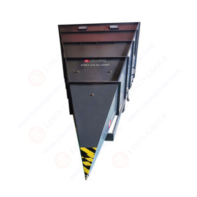
GTEM-1 GTEM Cell Chamber
Before the suction material is installed, the SE of the shielding room should be tested to confirm the shielding level of the shielding room. Similar to NSA65-6, the current standards for the test shielding effectiveness test are MIL -SD -285 and IEEE299-1997. Academic, IEEE299-1997 is considered to be after MIL -SD -285, which is written in 1956. It is more detailed and wider. Not only describes the test plan, but also has strict testing positions (doors, seams and other perforations). Because it is difficult to guarantee SE near perforation, we must pay special attention to the integrity of the shielding near the perforation.
3. The electromagnetic absorbing material electromagnetic absorbing material is installed on the wall of the shielding room and on the ceiling to reduce the surface electromagnetic reflection. Electromagnetic radiation was absorbed by the suction material when incident, and some electromagnetic energy was converted into thermal energy. Of course, there are some residual reflexes and can interfere with testing.
In SAC, there are currently two widely used broadband electromagnetic absorption materials. According to their working mechanisms, they are distinguished as: absorbing iron oxygen bodies radiated by magnetic fields and carbon foam radiating electric field radiation. Mixed materials are composed of these two materials. Of course, there are some special designs, but it is not widely used. Most of the foam -type suction materials are made into cone, while the mixed type is made into a pointed shape. The iron oxygen patch is generally installed on a non -conductive wall (usually plywood), so that the high -frequency performance of the patch can be improved. The design of broadband EMC suction materials is a complex process that needs to weigh and coordinate low -frequency and high -frequency performance, size and engineering cost. Generally, manufacturers often use trial methods to design suction materials. Through design, they try to work repeatedly. In order to accelerate the design process and make their economy, many manufacturers use computer -assisted design. Using computer -assisted design, absorbing the manufacturing and measurement of the material, just do not need to manage it. It only needs to be designed and the computer is optimized. If the accurate model is used, the parameters of a large number of suction materials are determined. Whether it is a large number of repeated attempt design methods or a computer for auxiliary design, high -quality suction materials can be produced.
Most manufacturers explain that when the performance of the suction material, only the situation of vertical incident is considered. This is a optimized data, which only has a good performance of direct vertical shooting with the suction material. But the situation of inclined shooting in SAC is more important than vertical. It is related to the attenuation of the waves on the surface of the shield. Most suction materials are very good for vertical incident. But considering the inclined shooting in SAC is more important than vertical. With the increase of the incident angle, the performance of the suction material has decreased significantly. Therefore, this is an important factor when designing the Dark Room. In SAC, the performance of the suction material is not only determined by the basic design performance of the suction material. The installation quality of suction materials also plays a great role. Especially the iron oxygen, whether or not the mixed design is or not, will reduce performance due to improper installation. Due to the limitation of the size of a single iron oxygen, there is a small air seam between the two close patchs.
These small gas seams are like magnetic resistance, reducing the continuity of the magnetic energy between the patch, and therefore reduce the absorption effect. In the case of careful installation, a single gas seam will be less than one -tens of millimeters wide. Large gas seams will cause a small decrease in small incident attenuation, so it allows some special parts on the wall of the shielded room to have a large reflection. In the design of the absorbing material and the Dark Radio Dark Room, the so -called gas seam effect must be considered, because the gas seams are often encountered in actual installation. Even if a small gas seam will reduce the performance of the iron oxygen patch, which makes the actual level lower than the theoretical level. The measurement of suction materials is an important part of confirming their performance. Due to the strict low -frequency performance requirements of SAC, the suction material must be confirmed to the performance of the lower limit to 30MHz. From 150MHz to 30MHz or lower, it can be measured with coaxial waveguide. In high frequency bands, other types of waveguide (100MHz and above) and the way of free space (higher than 800MHz) can be used for testing.
4. In order to build an SAC that meets the requirements of the venue attenuation, the measured returning venue attenuation values and the ideal open field (according to the standard ANSIC63.4-1992) are measured than 4DB. This indicator faces many challenges, especially in low frequency bands. The size of the electric field inhale material is small and the electromagnetic performance is very poor. Therefore, before the construction of the Dark Room, digital simulation needs to be used to confirm and optimize the design of the Dark Room. The manufacturer can choose to try to design, but this will consume a lot of time and cost. Digital simulation, through the combination of the correction of the performance measurement data of the built -in dark room, is an effective design tool for the designer of today’s radio wave room. In the middle and high sections of the operating frequency range, the electromagnetic waves incorporated into the suction material can be considered as a flat wave. In this case, using the method of ray tracking to simulate the performance of the Dark Room, it will get a credible calculation of the performance of the Dark Room. For low -frequency conditions, the assumptions of graphic waves are no longer effective.
For low -frequency range, there are two ways to perform the performance model of the radio waves: one is to simulate the ray tracking technology in high frequency, and the other is to perform Maxwell equations in the case of 3D in the shielding room equipped with a suction material. Solve. In the case of ray tracking, due to the low frequency performance of the suction material and the size of the radio wave room, multiple reflection must be considered. Because the test data of the low -frequency band suction material is difficult to measure than vertical conditions at any angle, the number simulation data is often used. It should be noted that the performance data of this simulation suction material is closely related to the measurement data of vertical incident to avoid system errors in the simulation of the radioir room. In the multi -stage ray tracking model, the performance simulation of the measured 10M radio dark chamber is better than the 3M radio -dark room. This is because the electrical space in the 10M radio room is large enough. Because the solution of the three -dimensional Maxwell equation is a deep and meticulous computing task, the finite element method or limited differences are usually used. These methods are divided into discrete units that need to be calculated in order to use Maxwell equations for operations. For low -frequency bands, the suction material is approximately low -frequency thin layer, which can reduce the difficulty of computing. However, the accuracy of this algorithm relies on the use of the suction material model, the test of the performance of the suction material, and a large amount of data. Theoretically, this method is accurate and reliable than the ray tracking method. However, compared with multi -stage ray technology, the installation and restrictions on the installation of wave suction materials and the restrictions on the Dark Room measurement cause uncertainty during the implementation process, and at the same time, the accuracy of actual design is limited.
The laboratory is built in the above parts. We introduced several major problems, including SAC’s design, shielding performance, suction materials, and radio dark room models. This part focuses on the overall implementation of these aspects. Multi -level reflex rays tracking methods have the advantages of convenient calculation. Applying this technology, designers can choose optimized design from many design drafts. An experienced design engineer can analyze and organize data to ensure the performance of the radio waves without considering the inherent restrictions of model -based technology.
When building an EMC test laboratory, a large space requires a large space to accommodate the dark room and related equipment. We also need to consider fire prevention facilities, elevated floors, and reinforced shielding rooms to enable the quality of the load absorbing material and ensure its integrity.
After the construction of SAC and related devices, it is necessary to verify its performance to prove that the OATS that replaces the ideal with SAC is feasible. In the people’s EMC facilities, the SAC performance test is based on the standard ANSIC63.4-1992, CISPR22, or the alternative method described in the relevant standards. These test procedures are confirmed by comparing the attenuation of the Dark Room and OATS to confirm the performance of the radio waves. The venue attenuation is the theory described by the alternative place in the standard, and the measurement is located in a static area around EUT on the turntable. The frequency range of this test program is determined according to the requirements of the EUT testing of the EUT test. After the initial verification is determined, the operation of SAC should be based on annual verification. The performance of SAC depends on many factors. One is the installation of the suction material. The gas seam effect of iron oxygen patch should be paid specially, especially in the door and other perforations, the suction material there is discontinuous. The arrangements of doors, interface boards and windows should also be careful. Be careful not to cause performance problems in the discontinuous place of the suction material, and do not have parasitic reflexes and launch caused by non -processing reflex substances. In addition, the floor should be very flat, and the electrical continuity should be guaranteed around the table.
When verifying the Dark Room, the antenna coefficient plays a strict role. In addition, after a long time, the absorbing material, especially the split bubble, will be tilted, and the performance has a small impact, but some negative effects. An important problem is that when choosing a manufacturer of a suction material or a dark room, you must have quality control. Because the performance of the suction material is the most important factor in the electromagnetic performance of SAC, it is necessary to pay attention to whether the manufacturer can ensure that the performance of each batch of suction materials produced in the factory is consistent. It is best to have a quality control program to ensure that the electromagnetic performance of each batch of suction materials is strictly tested within the low frequency range. In addition, the performance of the Dark dark Room is related to the installation quality of the suction material. Therefore, the quality of the experienced personnel must follow in the installation. Generally speaking, the EMC test device is not just SAC. According to the needs of budgets and experiments, the shielded control room and laboratory can also be increased. It can also increase the full radio dark room and the predicted radio -wave dark room that can also increase the resistance. The minimum is to have enough space to accommodate test equipment and operators.
In conclusion:
This article covers the general situation in the construction of SAC, but it does not cover all the issues involved in the construction of SAC. Some important issues, such as fire safety and structural integrity which need further study. In short, the construction of SAC is not a simple task, there are a number of factors affecting the SAC’s electromagnetic performance and function. Especially for the fully-adapted anechoic chamber, for the test distance of 3m or 10m, quality control, design ability and existing work performance play an important role in the selection of anechoic chamber manufacturers. In addition, the successful operation of EMC equipment is related to the use of test accessories (turntable, antenna, antenna, cable) and measuring instruments, and the experience of the experimenter is also important.
Lisun Instruments Limited was found by LISUN GROUP in 2003. LISUN quality system has been strictly certified by ISO9001:2015. As a CIE Membership, LISUN products are designed based on CIE, IEC and other international or national standards. All products passed CE certificate and authenticated by the third party lab.
Our main products are Goniophotometer, Integrating Sphere, Spectroradiometer, Surge Generator, ESD Simulator Guns, EMI Receiver, EMC Test Equipment, Electrical Safety Tester, Environmental Chamber, Temperature Chamber, Climate Chamber, Thermal Chamber, Salt Spray Test, Dust Test Chamber, Waterproof Test, RoHS Test (EDXRF), Glow Wire Test and Needle Flame Test.
Please feel free to contact us if you need any support.
Tech Dep: Service@Lisungroup.com, Cell/WhatsApp:+8615317907381
Sales Dep: Sales@Lisungroup.com, Cell/WhatsApp:+8618117273997

LISUN’s Motor-Operated Tool | Power Tool Testing solutions strictly comply with a range of core international standards, providing full support for safety and electromagnetic compatibility (EMC)...

LISUN’s electric toy testing solutions cover IEC 62115, EN 71-1, ASTM F963 standards. Including electrical, mechanical, flammability tests to ensure toy safety compliance globally.

LISUN’s transformer test solutions meet IEC 61558-1, IEC 60076-1, IEC 62041 standards. Covering safety, performance, EMC tests, ensuring transformers comply with global requirements.

LISUN’s energy meter testing solutions align with IEC 62052-11, IEC 62053 series standards. Covering safety, electrical, environmental, and EMC tests, we help manufacturers meet global compliance...

LISUN’s household and appliance switch testing solutions meet IEC 60669, IEC 61058, IEC 62271 standards. Covering electrical, mechanical & EMC tests for global compliance.
LISUN’s mobile and network test solutions include EMC/EMI testing, color glossiness measurement, IP waterproof/dustproof tests, IK impact tests, and environmental simulation, meeting international standards.

 中文简体
中文简体