LM-79 Moving Detector Goniophotometer (Mirror Type C)
LSG-6000

High Precision Rotation Luminaire Goniophotometer
LSG-1890B

High Precision Rotation Luminaire Goniospectroradiometer
LSG-1890BCCD

Goniophotometer for Automotive and Signal Lamps
LSG-1950

Goniophotometer for Traffic Signal Lamps
LSG-1950S

Compact Goniophotometer
LSG-1200A

Near Field Moving Detector Goniophotometer
LSG-1900B
Select an organization
to browse standards
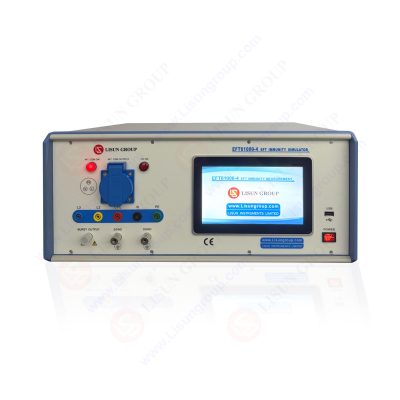
1. The mechanism of EFT Immunity Measurement and its impact on electronic products
The EFT immunity tester is a transient disturbance generated at the disconnection due to the insulation breakdown of the switch contact gap or the contact bounce when the inductive load (such as relay, contactor, etc.) is disconnected. When the inductive load is repeatedly switched on and off for many times, the pulse group will be repeated many times with the corresponding time interval. This kind of transient disturbance energy is small and generally does not cause damage to the equipment, but because of its wide spectrum distribution, it will affect the reliable operation of electronic and electrical equipment.
It is generally believed that the reason why the EFT Immunity tester pulse group causes the malfunction of the equipment is that the pulse group charges the semiconductor junction capacitance in the line. When the energy on the junction capacitance accumulates to a certain extent, it will cause the malfunction of the line and even the equipment.

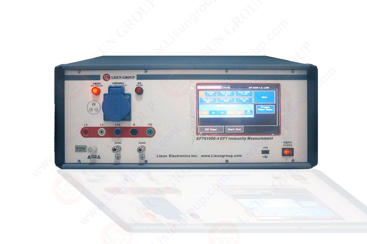
EFT61000-4_EFT Immunity Measurement
1.1. EFT Immunity Measurement and related requirements
Different electronic and electrical product standards have different requirements for EFT Immunity Measurement, but most of these standards directly or indirectly refer to GB/T17626.4- 1998 (idt IEC 61000-4-4:1995): ” EFT Immunity Measurement for Electromagnetic Compatibility Test and Measurement Technology”, a national basic standard for electromagnetic compatibility, and the test was carried out according to the test method. The following briefly introduces the content, test methods and related requirements of the standard.
1.2. Test objects:
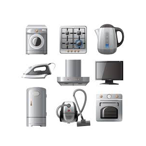
Immunity test for EFT Immunity Measurement of electronic and electrical equipment used in residential and commercial/industrial areas under operating conditions.
1.3. Test content:
Evaluate the performance of power supply ports, signal and control ports of electrical and electronic equipment when disturbed by repetitive fast transient bursts.
1.4. Test purposes:
A repetitive fast transient test is a test in which a burst of many fast transient pulses is coupled to the power, signal and control ports of electrical and electronic equipment. The main points of the test are the short rise time, repetition rate and low energy of the transient.
1.5. Test method:
Selective coupling/decoupling network to AC/DC power terminals to apply fast transient burst interference signals. Select capacitive coupling clips dedicated to EFT immunity testing for I/O signal, data and control ports to apply fast transient burst interference signals.
1.6. Test Environment:
The environmental conditions specified in this standard:
Ambient temperature: 15℃~35℃, relative humidity: 25%~75%RH, atmospheric pressure: 86kPa~106kPa.
1.7. Test implementation:
Power, signal and other functional power should be used within their rated range and in normal working condition. Select the corresponding test level and coupling method according to the port type of the EUT to be tested. Make the device under test under typical working conditions, and apply the test voltage to each port in turn according to the port of the device under test and its combination. Each combination shall be tested for different pulse polarities, and the test duration of each state shall not be less than 1min. Different product or product family standards may have specific provisions for the conduct of tests according to the characteristics of the product.
1.8. Test Results:
If the electric fast variable pulse group test fails, the following consequences may occur: cause the equipment to malfunction.

EFT Immunity Measurement
2. Reasons for the failure of the EFT Immunity Measurement
From the pulse burst test, the conduction difference/common mode interference test of the power line and the signal/control line is mainly carried out, but the waveform front edge of the interference pulse is very steep and the duration is very short, so it contains extremely rich high-frequency components. This results in a part of the interference escaping from the transmission cable during the transmission of the interference waveform, so that the device finally receives the combined interference of conduction and radiation.
The rising edge of the EFT Immunity Measurement waveform is very steep and contains a lot of high frequency components. In addition, since the test pulse is a pulse train that lasts for a period of time, it has a cumulative effect on the interference of the circuit. In order to resist transient interference, most circuits are equipped with an integrating circuit at the input end, which has a good effect on a single pulse. The inhibitory effect of , but cannot be effectively suppressed for a series of pulses.
a) The power supply is directly conducted into the device through the power line, resulting in excessive noise voltage on the power line of the circuit. When the live wire or the neutral wire is injected separately, there is differential mode interference between the live wire and the neutral wire, and this differential mode voltage will appear at the DC output of the power supply. When the live wire and the neutral wire are injected at the same time, there is only a common mode voltage. Since the input of most power supplies is balanced (whether it is a transformer input or a rectifier bridge input), the actual common mode interference is converted into a differential mode voltage. There are few components, and it has little effect on the output of the power supply.
b) In the process of conducting the interference energy on the current line, it is radiated to the space, and these radiated energy are induced to the adjacent signal cables, causing interference to the circuit connected by the signal cable (if this happens, it will often be directly directed to the signal cable. When a test pulse is injected, the test fails).
c) The secondary radiation energy generated when the interference pulse signal is transmitted on the cable (including the signal cable and the power cable) is induced into the circuit, causing interference to the circuit.
2.1 Corrective measures for passing the EFT Immunity Measurement
For pulse group interference, filtering (filtering of power lines and signal lines) and absorption (absorbing with ferrite cores) are mainly used. The ferrite core absorption scheme is very cheap and very effective, but pay attention to the placement of the ferrite core during the test, that is, the position where the ferrite core will be used in the future. Do not change it at will, because burst interference is not only a conducted interference, but more troublesome is that it also contains radiation components. Different installation positions, the escape of radiation interference is different and elusive. Ferrite cores are generally most effective at sources of interference and at the entrance to equipment. The following sections will be discussed according to the different ports.

2.2 Measures for power cord testing
The main way to solve the problem of power line interference is to install a power line filter at the power line entrance to prevent interference from entering the equipment. When the fast pulse is injected through the power line, it can be injected in a differential mode or in a common mode. The differential mode injection can generally be absorbed by differential mode capacitors (X capacitors) and inductor filters. If the voltage injected into the power line is a common-mode voltage, the filter must be able to suppress this common-mode voltage so that the device under test can pass the test smoothly.
Here’s how to suppress electrical fast pulses on power lines with a filter.
a) The chassis of the device is metal:
This situation is the easiest. Because the chassis is metal, there is a large stray capacitance between it and the ground plane, which can provide a relatively fixed path for the common mode current. At this time, as long as a power line filter containing a common-mode filter capacitor is installed at the entrance of the power line, the common-mode filter capacitor can bypass the interference and return it to the source of the interference. Because the common-mode filter capacitor in the power line filter is limited by the leakage current and has a small capacity, it mainly relies on the common-mode inductance to suppress the lower frequency components in the interference. In addition, since the ground wire between the equipment and the ground plane has a large inductance and has a large impedance to high-frequency interference components, whether the equipment is grounded or not generally has no effect on the test results. In addition to choosing a filter with good high-frequency performance, when installing the filter, pay attention to the filter should be close to the power inlet on the metal chassis to prevent the interference caused by the secondary radiation of the power line.
b) The equipment chassis is non-metallic
If the chassis of the device is non-metallic, a metal plate must be added at the bottom of the chassis to ground the common-mode filter capacitor in the filter. The common mode interference current path at this time forms a path through the stray capacitance between the metal plate and the ground plane. If the size of the device is small, it means that the size of the metal plate is also small, and the capacitance between the metal plate and the ground plane is small, which cannot play a good bypass role. In this case, it is mainly the inductance that comes into play. At this time, various measures need to be taken to improve the high-frequency characteristics of the inductor, and multiple inductors can be connected in series if necessary.
3. Measures to be taken for signal line test
When the fast pulse is injected through the signal/control line, it is a common mode injection method because of the use of capacitive coupling clip injection.
a) Signal cable shielding:
It can be seen from the test method that the interference pulse is coupled into the signal cable by capacitive coupling. The way to eliminate capacitive coupling is to shield the cable and ground it. Therefore, the condition for solving the electrical fast pulse interference by the method of cable shielding is that the cable shielding layer can be reliably connected with the reference ground plane in the test. This condition is easily met if the equipment enclosure is metal and is grounded equipment. When the casing of the equipment is metal, but not grounded, the shielded cable can only suppress the high-frequency components in the electrical fast pulse, which is grounded through the stray capacitance between the metal casing and the ground. If the case is a non-metallic case, the method of shielding the cables has little effect.
b) Install a common mode choke on the signal cable:
The common mode choke coil is actually a low-pass filter, and only when the inductance is large enough can it have an effect on the electrical fast pulse group. However, when the inductance of the choke coil is large (often the number of turns is large), the stray capacitance is also large, and the high frequency suppression effect of the choke coil is reduced. The electrical fast pulse waveform contains a lot of high frequency components. Therefore, in actual use, it is necessary to pay attention to adjusting the number of turns of the choke coil, and if necessary, use two choke coils with different turns in series to take into account the requirements of high frequency and low frequency.
c) Install a common mode filter capacitor on the signal cable. This filtering method has a better effect than a choke coil, but requires a metal chassis as the ground for the filter capacitor. In addition, this method will attenuate the differential mode signal to a certain extent, so you need to pay attention when using it.
d) Partial shielding of sensitive circuits. When the chassis of the equipment is a non-metallic chassis, or the shielding and filtering measures of the cables are not easy to implement, the interference can be directly coupled into the circuit. In this case, only partial shielding of sensitive circuits can be performed. The shield should be a complete hexahedron.
Lisun Instruments Limited was found by LISUN GROUP in 2003. LISUN quality system has been strictly certified by ISO9001:2015. As a CIE Membership, LISUN products are designed based on CIE, IEC and other international or national standards. All products passed CE certificate and authenticated by the third party lab.
Our main products are Goniophotometer, Integrating Sphere, Spectroradiometer, Surge Generator, ESD Simulator Guns, EMI Receiver, EMC Test Equipment, Electrical Safety Tester, Environmental Chamber, Temperature Chamber, Climate Chamber, Thermal Chamber, Salt Spray Test, Dust Test Chamber, Waterproof Test, RoHS Test (EDXRF), Glow Wire Test and Needle Flame Test.
Please feel free to contact us if you need any support.
Tech Dep: [email protected], Cell/WhatsApp:+8615317907381
Sales Dep: [email protected], Cell/WhatsApp:+8618117273997

LISUN’s Motor-Operated Tool | Power Tool Testing solutions strictly comply with a range of core international standards, providing full support for safety and electromagnetic compatibility (EMC)...

LISUN’s electric toy testing solutions cover IEC 62115, EN 71-1, ASTM F963 standards. Including electrical, mechanical, flammability tests to ensure toy safety compliance globally.

LISUN’s transformer test solutions meet IEC 61558-1, IEC 60076-1, IEC 62041 standards. Covering safety, performance, EMC tests, ensuring transformers comply with global requirements.

LISUN’s energy meter testing solutions align with IEC 62052-11, IEC 62053 series standards. Covering safety, electrical, environmental, and EMC tests, we help manufacturers meet global compliance...

LISUN’s household and appliance switch testing solutions meet IEC 60669, IEC 61058, IEC 62271 standards. Covering electrical, mechanical & EMC tests for global compliance.
LISUN has all equipment according to the IEC60669 measurement, including environmental chamber, IP code waterproof dustproof test, switch lift test, etc.

 中文简体
中文简体