
LM-79 Moving Detector Goniophotometer (Mirror Type C)
LSG-6000

High Precision Rotation Luminaire Goniophotometer
LSG-1890B

High Precision Rotation Luminaire Goniospectroradiometer
LSG-1890BCCD

Goniophotometer for Automotive and Signal Lamps
LSG-1950

Goniophotometer for Traffic Signal Lamps
LSG-1950S

Compact Goniophotometer
LSG-1200A

Near Field Moving Detector Goniophotometer
LSG-1900B
Select an organization
to browse standards
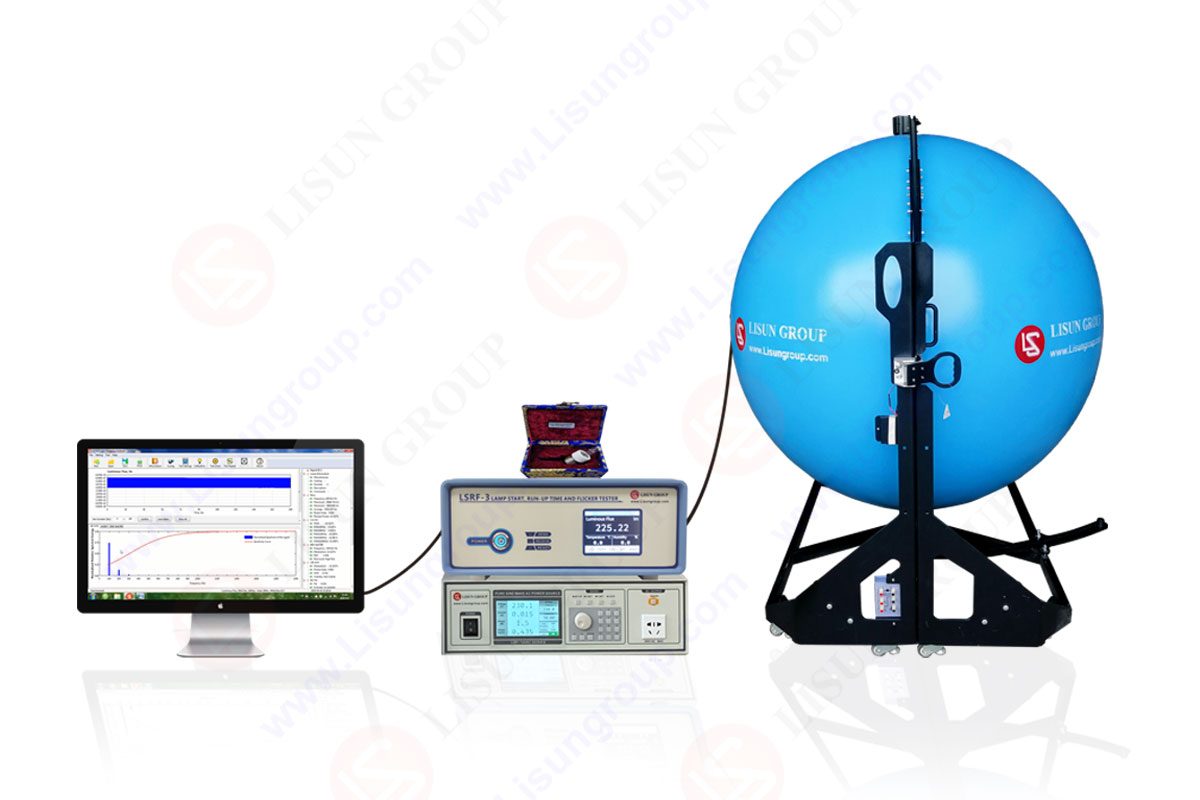
LISUN’s LSRF-3
Because the LSRF-3 is equipped with a Class A fast photometric probe, the sampling rate can reach 100kHz. It fully complies with BASIC, Energy Star V2.1, IEC-Pst, CA CEC, ASSIST, CIE SVM, IEEE Std 1789, and other standards. It is suitable for testing the flicker of LED lights and lamps, energy-saving lighting, and so on.
According to EU directives 1494/2012, 2009/125/EC, EU2019/2015 – EU2019/2020, and IEC60969 “Self- ballasted Lamps for General Lighting Services-Performance Requirements” in conjunction with LISUN’s LSP-500VARC AC Power Source (With Trigger Function), it is also possible to assess the start and run-up time of lamps.

LSRF-3_Lamp Start, Run-up Time and Flicker Test System
Application of LSRF-3
High Speed Camera Test Mode – To compare display refresh behavior
This test requires a camera with a high-speed video feature (480fps or higher). High Speed Video of Light Boost is an example of a recording. This test is important for updating the capture display, including scan out behavior. Full-screen mode should be used with caution.
Oscilloscope – To measure the display GtG pixel responsiveness
This mode works well with photodiode oscilloscopes. It reduces the flicker to your desired flicker rate. Because LCD pixel response might overlap many refresh cycles, this is advantageous.
Mouse Latency – To compare the latency of same-system adjustments
Evaluate the lag of various computer configurations using a high-speed camera that records both the screen and a quick touch on the mouse button. When you click the mouse, this test will appear. This can be done with a high-speed camera to assess relative latency discrepancies between systems and/or parameter modifications. Browser lag, graphics driver lag, display lag, refresh interval granularity, camera frame rate granularity, display scan out latency, and even windowed versus full screen mode are all error margins.
At-home flicker test
There are a handful of simple techniques to assess for LED flicker at home to avoid unpleasant illumination and potential health risks.
To begin, use your smartphone camera to execute a basic flicker test. Turn it on and look at the image taken on the screen while aiming it at the light source in question. If you see a succession of black and light bands gently moving across the screen, your light is flickering. If the bands are barely discernible, you are fine. Smartphone cameras can collect images at a distinct frequency, making them dependable tools that clearly register when there is no light.
Applicability
All integrated and externally ballasted compact fluorescent lamps (CFLs), integrated LED lamps, LED light engines, and LED luminaires as described in the ENERGY STAR Eligibility Criteria for Lamps and ENERGY STAR Eligibility Criteria for Luminaires are subject to this start time test method. Individual LED drivers are not affected.
Definitions
The integrated or externally ballasted CFL, integrated LED lamp, LED light engine, or LED luminaire that is undertaking the start time test is referred to as the Device Under Test (DUT).
Start Time
The interval between applying power to DUT and the moment at which light output reaches 98% of the initial plateau for fluorescent DUTs. The point at which the light source is constantly lighted, and the light output is either constant or growing in solid-state lighting DUTs. The initial plateau is the point at which the average increase in light output over time plateaus (reduces in slope). Based on the output trace, this can be computed theoretically or visually.
Measurement methods and reference documents
• Illuminating Engineering Society, New York, IES LM-66-14: 2014. Method for Electrical and Photometric Measurements of Single-Based Compact Fluorescent Lamps, Approved by IES.
• IES LM-79-08: Illuminating Engineering Society, New York, 2008. IES Approved Method for Solid-State Lighting Product Electrical and Photometric Measurements.
• IES LM-54-12: 2012. Illuminating Engineering Society, New York, IES Guide on Lamp Seasoning.
For this testing, DUTs having integral controls (e.g., motion sensors, photosensors, wireless control, standby mode, or connected functionality) may be disabled or bypassed.
Test setup
Instrumentation and flicker Test Setup:
• AC or DC power supply that is regulated (as applicable to the DUT)
• Data storage oscilloscope with several channels
• Useful attenuator probe (s)
• photodetector

Compact fluorescent lamps (CFL) must be seasoned for one hundred hours prior to the initial readings in line with IES LM-54-12. CFLs must be pre-burned according to IES LM-66-14. SSL sources must not be aged.
Power Requirements for Start Time Measurements
The power requirements must be in accordance with IES LM-66-14 or LM-79-08, as applicable. When selecting a power source for use with integrated lamps and luminaires, the Volt-Amp capacity of the power supply must be specified with an acceptable power factor.
Storage
Lamps and luminaires must be stored at 25°C 5°C for at least 16 hours before to the test, after which the temperature range must be 25°C 1°C for at least two hours. CFL light and ballast (if applicable) samples must be turned off for 20 hours 4 hours before testing.
If the CFL lamp and ballast sample has been turned off for more than 24 hours, it must be run for 3 hours and then turned off for 20 hours 4 hours before the test.
Ambient Temperature
All tests must be conducted at a temperature of 25°C 1°C. Drafts should be maintained to a bare minimum.
Power Meter
Power meters must be capable of measuring in accordance with the applicable standards of IES LM-66-14 or IES LM-79-08.
Environmental Conditions
The flicker testing environment must be clean and free of excessive dust and dampness.
Orientation
Test samples in the orientation(s) indicated by the ENERGY STAR specification or, if different, in the position stated by the manufacturer.
Sample Selection
Samples must be indicative of the typical product of the producer. Before flicker testing, the samples must be carefully cleaned and inspected. Flaws or inconsistencies in the DUT samples must be documented.
Test conduct
Photometric Measurements
1. Refer to IES LM-66-14 or IES-LM-79-08 as applicable for integrating sphere measurements:
The photodetector utilized for photometric measurements on non-integrating spheres shall be a silicon detector calibrated to closely fit the Commission Internationale de l’Eclairage (CIE) spectrum luminous efficiency curve (V.
2. Fluorescent System Transfer After Seasoning:
Fluorescent sources and ballasts must be stored in accordance with the requirements in section 5D above before being moved to the start time testing equipment. During the transfer from seasoning, take care to maintain lamp position and prevent shaking or bumping the lamp.
Test procedure
1. Place the DUT in the testing environment. If applicable, the ballast or driver may be located outside of the test environment.
2. To measure non-integrating spheres, orient the photocell so that it observes the main body of the discharge tube or array (as applicable). Shield yourself from stray light as needed.
3. See test conduct section 6 for integrating sphere measurements.
4. When evaluating a covered CFL, the photocell only needs to observe the sample’s exterior luminous face.
5. When testing DUTs that have sensors (e.g., motion sensors, photosensors), the sensors may be disabled or bypassed.
6. Connect a probe from an oscilloscope to the sample in order to gauge the input voltage and light output. G. Configure the scope so that the input voltage signal triggers it. Set trigger level at 10V.
7. Set the power supply to the DUT’s rated voltage and frequency. If a range is specified, the test sample should be taken at the middle of the range.
8. Determine the suitable voltage and time basis parameters using an exemplar sample. The recommended beginning time basis is 200 ms/div.
9. Connect the DUT to the rated voltage/frequency.
10. Record the input voltage and light output waveform that were used to calculate the starting time.
11. Note the Start Time.
Testing report
Start The following test information must be included in the time test report data:
A. Light Engine, Lamp, and Ballast/Driver (if applicable) Name(s) of the manufacturer(s) and product identification
B. Testing facility name and address
C. Date of the test
D. DUT testing orientation (if applicable)
E. Voltage for testing (V)
F. Frequency of testing (Hz)
G. Time basis (ms/div) configuration
H. Input voltage and light output waveform used to calculate start time
I. Beginning Time (ms)
J. Indicate whether sensors were deactivated or bypassed for this testing and provide any relevant methods.
The need for Flicker test
Different scenarios necessitate a different emphasis on flicker, which is mostly determined by geography, experience, probable exposure time, and the type of activity taking place.
There is limited evidence of flicker complaints in an outside context, such as a street or a parking lot, and light sources with a high flicker may not have a detrimental influence in such situations. However, if the outdoor venue holds evening athletic activities, a low flicker light source is required to avoid stroboscopic effects on the field.
Moving inside, in an office or educational setting where people are exposed to artificial light for extended periods of time while completing complicated tasks, low flicker may reduce eye strain and be useful to migraine patients.
In an industrial setting, the situation must be carefully considered once more. Low flicker is preferable but not required in a warehouse with few moving objects and few visual duties.
Low flicker is a critical requirement in a manufacturing facility with many moving components of machinery to avoid mistaking moving parts.
Energy Conservation Requirements
The lighting industry has developed dimmable solutions to assist save energy based on the many types of situations and light needs.
Any dimming control, from a wall-box dimmer to an automated daylight harvesting system, has the potential to cause system mismatch and add to the flicker. A phase-cut, wall-box dimmer has the greatest potential for additional flicker, although other approaches can contribute some flicker as well.
A thorough understanding of light source and/or luminaire flicker characteristics, along with sound procedures when considering space tasks and lighting selection. This may serve to lessen user discomfort even though the application implications of flicker have not been completely investigated. This is especially important for LED installations that might be used for an extended period.
Although numerous documents giving measurement metrics on this topic have been released, there are some inconsistencies among them. The primary documents and key aspects of each are summarized here.
FAQs
What exactly is a light test?
Loop-mediated isothermal amplification (LAMP) is a single-tube DNA amplification technology that is a low-cost, fast alternative to RT-qPCR. LAMP with reverse transcription (RT-LAMP) combines LAMP with a reverse transcription (RT) step to detect RNA.
What exactly is a flicker test?
A visual field test method known as flicker perimetry evaluates a subject’s capacity to recognize flicker, or the alternation of light and dark stimuli, at various points in the field of vision.
What is the purpose of flicker?
Flicker is purposely utilized by developers on low-end computers to generate the illusion of more objects or colors/shades than the system supports, or as a quick technique to simulate transparency.
Lisun Instruments Limited was found by LISUN GROUP in 2003. LISUN quality system has been strictly certified by ISO9001:2015. As a CIE Membership, LISUN products are designed based on CIE, IEC and other international or national standards. All products passed CE certificate and authenticated by the third party lab.
Our main products are Goniophotometer, Integrating Sphere, Spectroradiometer, Surge Generator, ESD Simulator Guns, EMI Receiver, EMC Test Equipment, Electrical Safety Tester, Environmental Chamber, Temperature Chamber, Climate Chamber, Thermal Chamber, Salt Spray Test, Dust Test Chamber, Waterproof Test, RoHS Test (EDXRF), Glow Wire Test and Needle Flame Test.
Please feel free to contact us if you need any support.
Tech Dep: Service@Lisungroup.com , Cell/WhatsApp:+8615317907381
Sales Dep: Sales@Lisungroup.com , Cell/WhatsApp:+8618117273997
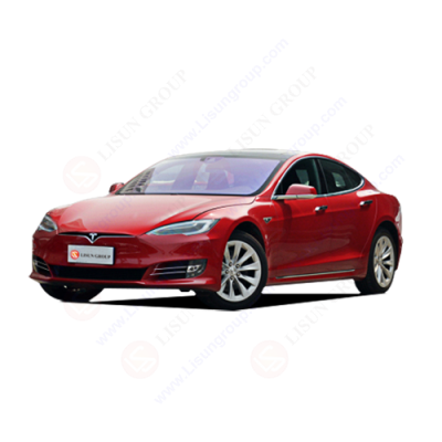
LISUN’s automotive electronics test solutions cover photometric/colorimetric testing, EMC immunity tests, IP waterproof/dustproof tests, and environmental simulation, meeting ISO, SAE, ECE standards.

LISUN provide full test solutions for HID lamp, including integrating sphere system, goniophotometer system, EMI EMC chamber, HID ballast tester, electrical safety test, etc.

Lisun can supply full test solutions for fluorescent lamp, including integrating sphere system, goniophotometer system, EMI EMC test, electronic ballast tester, electrical safety test, etc.

For the CFL design and manufactory, LISUN can supply a full quality control test solution, including photometric, colorimetric, electricity, flicker, IES candela distribution, surge test, electrical...

 中文简体
中文简体