LM-79 Moving Detector Goniophotometer (Mirror Type C)
LSG-6000

High Precision Rotation Luminaire Goniophotometer
LSG-1890B

High Precision Rotation Luminaire Goniospectroradiometer
LSG-1890BCCD

Goniophotometer for Automotive and Signal Lamps
LSG-1950

Goniophotometer for Traffic Signal Lamps
LSG-1950S

Compact Goniophotometer
LSG-1200A

Near Field Moving Detector Goniophotometer
LSG-1900B
Select an organization
to browse standards
8.4 Limitation of voltage, current or energy of IEC60601-1
8.4.1 PATIENT CONNECTIONS intended to deliver current
The limits specified in 8.4.2 do not apply to currents that are intended to flow through the body of the PATIENT to produce a physiological effect during NORMAL USE.

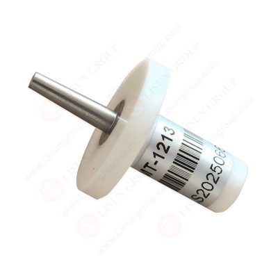
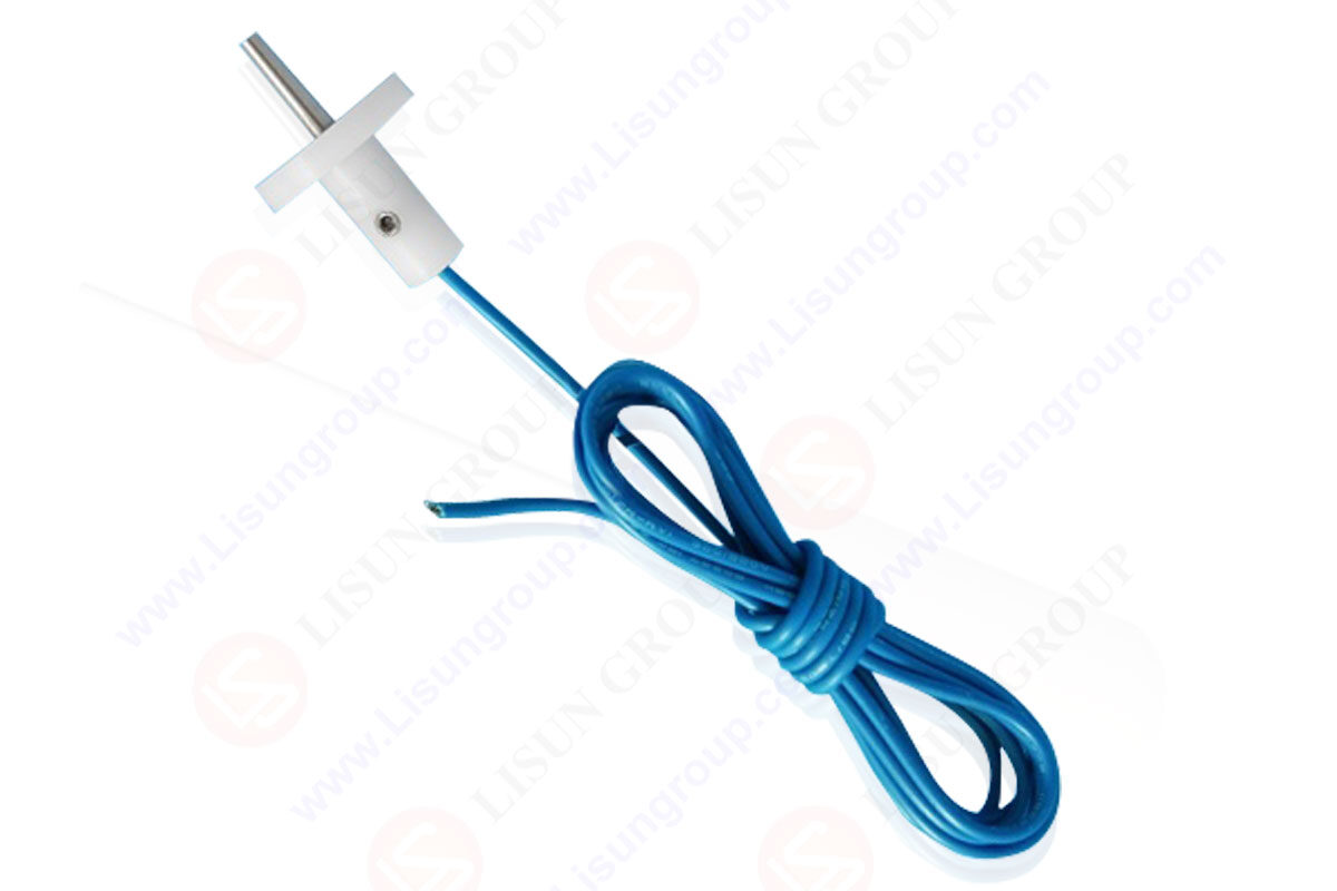
SMT 1213C_AL
8.4.2 ACCESSIBLE PARTS and APPLIED PARTS
a) The currents from, to or between PATIENT CONNECTIONS shall not exceed the limits for PATIENT LEAKAGE CURRENT and PATIENT AUXILIARY CURRENT specified in Table 3 and Table 4 when measured as specified in 8.7.4.
Compliance is checked by measurement according to 8.7.4.
b) The LEAKAGE CURRENTS from, to or between ACCESSIBLE PARTS shall not exceed the limits for TOUCH CURRENT specified in 8.7.3 c) when measured as specified in 8.7.4.
Compliance is checked by measurement according to 8.7.4.
c) The limits specified in b) above do not apply to the following parts if the probability of a connection to a PATIENT, either directly or through the body of the OPERATOR, through which a current exceeding the allowable TOUCH CURRENT could flow, is negligible in NORMAL USE, and the instructions for use instruct the OPERATOR not to touch the relevant part and the PATIENT simultaneously:
-accessible contacts of connectors;
-contacts of fuseholders that are accessible during replacement of the fuse;
-contacts of lampholders that are accessible after removal of the lamp;
-parts inside an ACCESS COVER that can be opened without the use of a TOOL, or where a TOOL is needed but the instructions for use instruct any OPERATOR other than SERVICE PERSONNEL to open the relevant ACCESS COVER.
EXAMPLE 1 Illuminated push-buttons
EXAMPLE 2 Indicator lamps
EXAMPLE 3 Recorder pens
EXAMPLE 4 Parts of plug-in modules com
EXAMPLE 5 Batteries
For such parts, the voltage to earth or to other ACCESSIBLE PARTS shall not exceed 42.4V peak a.c. or 60 V d.c. in NORMAL CONDITION or in SINGLE FAULT CONDITION.The d.c. limit of 60 V applies to d.c. with not more than 10 % peak-to-peak ripple. If the ripple exceeds that amount, the 42,4 V peak limit applies. The energy shall not exceed 240 VA for longer than 60 s or the stored energy available shall not exceed 20J at a potential-up
NOTE 1 If voltages higher than the limits specified in 8.4.2 c) are present, the LEAKAGE CURRENT limits referred to in 8.4.2 b) apply.
Compliance is checked by inspection of the instructions for use and by measurement.
If the ME EQUIPMENT has sir/sor conncctors or soparatc power supply output conncctors, measure the voltage of all conductive ACCESSIBLE PARTS of the SIP/SOP connectors or power output connectors to earth:
– Connect a resistor of 10kΩ±500 Ω (8 W for measurements up to 280Vr.m.s.) between the SIP/SOP-pin (or other output connector) to earth.
-Connect in parallel to the 10kΩ resistor a peak voltmcter or an oscilloscope to measure the voltage.
The voltage and energy limits specified in c) above also apply to:
-internal parts, other than contacts of plugs, connectors and socket-outlets, that can be touched by the test pin shown in Figure 8 inserted through an opening in an ENCLOSURE; and
– internal parts that can be touched by a metal test rod with a diameter of 4-0.05 mm and a length of 100 +05 mm, inserted through any opening in the top of an ENCLOSURE or through any opening provided for the adjustment of pre-set controls that-may can be adjusted by the RESPONSIBLE ORGANIZATION in NORMAL USE by using a TOOL.
See also 8.9.4 concerning the measurement of CREEPAGE DISTANCES and AIR CLEARANCES through slots or openings in external parts to the standard test finger.
Compliance is checked by inserting the test pin or the test rod through relevant openings. The test pin is inserted in every possible position with minimal force (not more than 1N).
The test rod is inserted in every possible position through openings provided for the adjustment of pre-set controls that can be adjusted lby the RESPONSIBLE ORGANIZATION in NORMAL USE, in case of doubt with a force of 10 N.
If the instructions for use specify that a particular TOOL is to be used, the test is repeated with that TOOL.
The test rod is also freely and vertically suspended through any opening in the top of an ENCLOSURE.

IEC60601-1 Figure 8 Test Pin
Lisun Instruments Limited was found by LISUN GROUP in 2003. LISUN quality system has been strictly certified by ISO9001:2015. As a CIE Membership, LISUN products are designed based on CIE, IEC and other international or national standards. All products passed CE certificate and authenticated by the third party lab.
Our main products are Goniophotometer, Integrating Sphere, Spectroradiometer, Surge Generator, ESD Simulator Guns, EMI Receiver, EMC Test Equipment, Electrical Safety Tester, Environmental Chamber, Temperature Chamber, Climate Chamber, Thermal Chamber, Salt Spray Test, Dust Test Chamber, Waterproof Test, RoHS Test (EDXRF), Glow Wire Test and Needle Flame Test.
Please feel free to contact us if you need any support.
Tech Dep: [email protected], Cell/WhatsApp:+8615317907381
Sales Dep: [email protected], Cell/WhatsApp:+8618117273997

LISUN’s Motor-Operated Tool | Power Tool Testing solutions strictly comply with a range of core international standards, providing full support for safety and electromagnetic compatibility (EMC)...

 中文简体
中文简体