
LM-79 Moving Detector Goniophotometer (Mirror Type C)
LSG-6000

High Precision Rotation Luminaire Goniophotometer
LSG-1890B

High Precision Rotation Luminaire Goniospectroradiometer
LSG-1890BCCD

Goniophotometer for Automotive and Signal Lamps
LSG-1950

Goniophotometer for Traffic Signal Lamps
LSG-1950S

Compact Goniophotometer
LSG-1200A

Near Field Moving Detector Goniophotometer
LSG-1900B
Select an organization
to browse standards
How can we classify if an electronic system will disturb our surroundings or not? Independently of any measurement technique, we need a measuring instrument to characterize the disturbances. This instrument is called EMI Receiver. EMI stands for electromagnetic interference. So, an EMI receiver can measure interferences that may disturb an electronic system.

EMI Test Receiver
On the display of an EMI receiver, we see a graph where the x-axis shows the frequency on a logarithmic scale, and the y-axis shows the measured interference in dbuV. In addition, some limit lines can be displayed, which must not be exceeded by the input signal. Different standards propose different limit lines and different methods how to measure the interference.
We can differ between the two categories. First, conducted emissions where we directly connected our DUT ( Device under test) to the EMI receiver. Second, radiated emissions where the EMI receiver acts as an antenna.

Block Diagram of an EMI Receiver EMI-9KB
The first component which the input signal sees is an attenuator. In EMI receiver EMI-9KB, this block is often set automatically to prevent an overload of the receiver. You must consider that not just amplifiers can go into the compression. Frequency mixers, which also contain the active components, can also produce overtones.
A pre-selector follows the attenuator. It is some kind of switchable filter bank where an appropriate filter is chosen automatically. We need this pre-selector for two reasons. The first is once again to prevent the overload conditions from the signals outside of the range of interest. The second is to prevent spurious mixing products or intermodulation distortion products.
Every non-ideal filter and our frequency mixer reduce the signal strength. Therefore, we need to amplify our signal to prevent a loss of resolution in the y-axis. One important component is our resolution bandpass filter within the intermediate frequency, abbreviated by IF. The CISPR standard defines the bandwidth of our filter for different frequency ranges.
These ranges are also called bands in the CISPR standard and are labelled with the letters A to E. Different settings must be chosen according to each band’s standard. Luckily, most EMI receivers have those settings automatically predefined.
But, how is the shape of our resolution bandwidth filter defined? We need to think back to our bandpass filter and mirror that shape vertically to answer this question. Now, the standard is defining some borders, here in red, which our filter shape must fulfil. The resolution bandwidth is also called the 6dB bandwidth when handling EMI receivers. The RBW is the bandwidth approximately 6dB away from the peak.
Conducted emissions are defined as the noise currents generated by the Device-Under-Test (DUT) through the power cord or harness propagation to other components/systems or power grid. We can measure these noise currents using either the voltage or the current method.
Purpose of Conducted Emissions Testing
Conducted Emission tests are used for testing that portion of electromagnetic energy created by the device that is conducted onto the power supply cord. This test aims to restrict the amount of interference that your device can couple back onto a power supply.

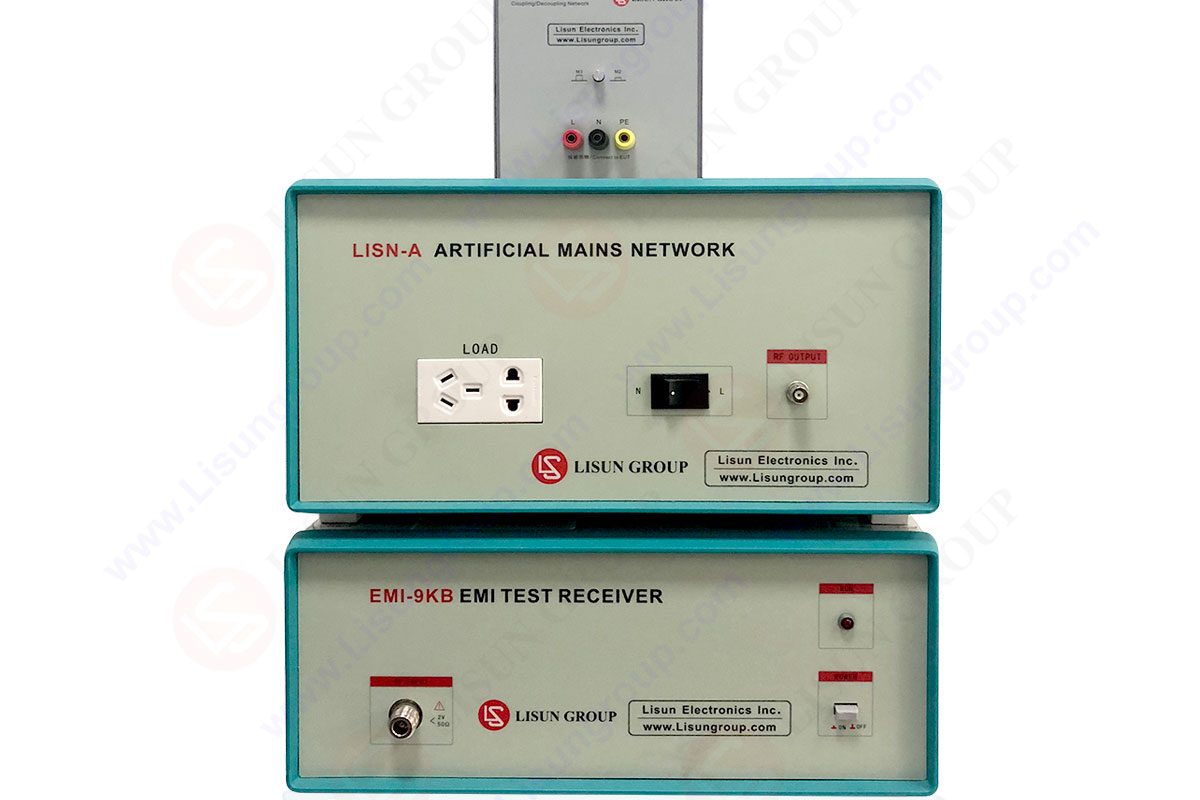
Place your product on the table. While the line impedance stabilization network is present either on the ground or it might stand on the floor if the testing equipment is large. A spectrum analyzer is directly connected with the LISUN’s RF connector for the prevention of damage from the voltage spikes.
There are numerous similarities between both the devices. We are going to discuss some of the most important differences here.
• First, we have some additional components like pre-selector or different detectors, which you may not find in the spectrum analyzers.
• The final results shown on the EMI receiver display are generally given in dBuV instead of dBm or dBmW, as it is often used for spectrum analyzers.
• Spectrum analyzers usually sweep continuously through the frequencies. On the other hand, an EMI receiver performs this procedure stepwise and remains at each frequency step for a certain predefined time.
• The CISPR 16-1 standard defines how both the resolution bandwidth and the step size must be chosen correctly.
• As an example, let us consider that we want to start our measurement at 150 kHz. Here, the correct resolution bandwidth according to the requirements defined in the standard must be chosen at 9 kHz.
• The step size is usually half the resolution bandwidth, but some standards may ask for even the narrower steps.
• But in contrast to the spectrum analyzer, we do not start immediately from this 150 kHz frequency position but remain here until the predefined measuring time has elapsed.
• This measuring time should be chosen at least 3 times when our device under test needs to execute one full operation cycle.
Rohde Schwarz EMI test receiver is an EMI test receiver built for the measurement of electromagnetic disturbances using conventional stepped scans or ultrafast FFT-based time domain scans. It also acts as a powerful signal and spectrum analyzer.
One of the main areas developed on the esrp to allow the users to access these functions is the use of a very simple and straightforward automation setup. The test automation function in Rohde Schwarz EMI test receiver allows the users from one simple screen to set up the scan parameters for frequency ranges.
LISUN EMI test receiver is a main test system for EMI (Electromagnetic Interference) testing. The EMI-9KB is manufactured by LISUN and produced by the full closure structure and strong electro-conductibility material. This EMI Test receiver has a high shielding effect.
Spectrum analyzers do not possess a built-in preamplifier. EMI receivers have a preamplifier built in after the preselection stage. Therefore, they have a much lower noise floor figure.
An EMI receiver is defined as an electronic noise that interferes with the cable signals and reduces the signal integrity. Electromagnetic radiation sources generate this receiver.
Lisun Instruments Limited was found by LISUN GROUP in 2003. LISUN quality system has been strictly certified by ISO9001:2015. As a CIE Membership, LISUN products are designed based on CIE, IEC and other international or national standards. All products passed CE certificate and authenticated by the third party lab.
Our main products are Goniophotometer, Integrating Spheres, Spectroradiometer, Surge Generator, ESD Simulator Guns, EMI Receiver, EMC Test Equipment, Electrical Safety Tester, Environmental Chamber, Temperature Chamber, Climate Chamber, Thermal Chamber, Salt Spray Test, Dust Test Chamber, Waterproof Test, RoHS Test (EDXRF), Glow Wire Test and Needle Flame Test.
Please feel free to contact us if you need any support.
Tech Dep: Service@Lisungroup.com, Cell/WhatsApp:+8615317907381
Sales Dep: Sales@Lisungroup.com, Cell/WhatsApp:+8618117273997

LISUN’s Motor-Operated Tool | Power Tool Testing solutions strictly comply with a range of core international standards, providing full support for safety and electromagnetic compatibility (EMC)...

LISUN’s transformer test solutions meet IEC 61558-1, IEC 60076-1, IEC 62041 standards. Covering safety, performance, EMC tests, ensuring transformers comply with global requirements.

LISUN’s household and appliance switch testing solutions meet IEC 60669, IEC 61058, IEC 62271 standards. Covering electrical, mechanical & EMC tests for global compliance.

For the CFL design and manufactory, LISUN can supply a full quality control test solution, including photometric, colorimetric, electricity, flicker, IES candela distribution, surge test, electrical...

 中文简体
中文简体