
LM-79 Moving Detector Goniophotometer (Mirror Type C)
LSG-6000

High Precision Rotation Luminaire Goniophotometer
LSG-1890B

High Precision Rotation Luminaire Goniospectroradiometer
LSG-1890BCCD

Goniophotometer for Automotive and Signal Lamps
LSG-1950

Goniophotometer for Traffic Signal Lamps
LSG-1950S

Compact Goniophotometer
LSG-1200A

Near Field Moving Detector Goniophotometer
LSG-1900B
Select an organization
to browse standards
The determination of the luminous internsity distribution involves the use of a co-ordinate system in order to define the direction in which the intensity measurements are made. The systems used a spherical co-ordinate system with the center coincident with the photometric center of luminaires.
From a general point of view the co-ordinate system consists in a group of planes with a single of intersection: the polar axis. In this system a direction in space is characterized by two angles: the angle between the plane taken as a conventional and the half-plane containing the considered direction; and the angle between the polar axis and the considered direction or the conmplement of this angle.
The orientation of this system with respect to the first axis and the second axis of the luminaire is chosen with particular regards to the type of the luminaire, to the type of luminaire, to the type of lamp, to the mounting attitude of the luminaire and its application, in order to perform more accurate measurement or to simplify the consequent lighting calculations.
The definitions below can make the expression of co-ordinate system conveniently so as to give help for the mounting of lamps and luminaires.
The second axis (also auxiliary axis): an axis going through the photometric centre is perpendicular to the first axis, linked to the luminaire and used together with the first axis for defining the attitude of the luminaire.
A third axis: an axis going through the photometric centre is perpendicular to the two first axes,and also used in defining the attitude of a luminaire.
For a certain lamp or luminaire, the first axis and second axis are defined by manufacturers or photometric laboratories.
The first axis (also reference axis): an axis going through the photometric centre is used in photometric measurements as a reference direction to correlate the photometric measurements with the attitude of the luminaire.

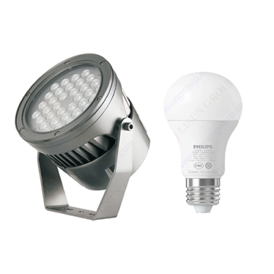
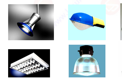
Test sample
The types of Goniophotometers can be basically divided into Type A, Type B and Type C. For a detailed description, please refer to the 1987 edition of CIE 70. The difference between them lies in the way the lighting equipment rotates during the measurement and the photometric data obtained during this measurement.

The totality of A-planes is a group of planes for which the line of intersection (polar axis) goes through the photometric center, and is perpendicular to the plane containing the first and the second axis of the luminarie. The first axis of the luminaries lies in the A=0º half-plane, and usually in the directionα=0º. The second axis of the luminarie goes through LSG-1890B/LSG-1800A User’s Manual Copyright from LISUN. Copy or spread without authorization is prohibited. The photometric center and is perpendicular to A=0º plane. The system of A-planes is coupled rigidly to the light source and follows its tilt if the luminaire is tilted.
The A-α system is characterized by the tilt angle of plane A and the angle in the plane α, which is the angle between the direction and commonality axis in A-planes. LISUN LSG-1890B/LSG-1800A goniophotometer can achieve the measurement in A-α system, and it is applicable for automobile, signal light and etc. As the first axis is usually horizontal, it can be express in another form (X-Y system).

A-α system

X-Y system
The totality of B-planes is a group of planes for which the line of intersection (polar axis) goes through the photometric center and is parallel to the second axis of the luminarie. The first axis of the luminarie lies in the B=0º half-plane, and usually in the direction β=0º. The second axis of the luminarie is coincident with the line of intersection of the B-planes. The system of B-planes is coupled rigidly to the light source and follows its tilt if the luminaire is tilted.
The B-β system is characterized by the tilt angle of plane B and the angle in the plane β, which is the angle between the direction and commonality axis in B-planes. LISUN LSG-1800A and LSG-1890B goniophotometer systems can achieve the measurement in B-β system, and it is applicable for floodlights generally. As the first axis vertical usually lay horizontal, it can be expressed in another form: V-H system.

B-β system

V-H system
The totality of C-planes is a group of planes for which the line of intersection (polar axis) is the vertical line through the photometric center. The polar axis is not limited to but usually coincides with the first axis of the luminarie. The system of C-planes is oriented rigidly in space and does not follow a tilt of the luminarie. The line of intersection of C planes is only perpendicular to the lines of intersection of the A- and B-planes for zero tilt of the light source.
The C-γ system is characterized by the tilt angle of plane C and the angle in the plane γ, which is the angle between the direction and commonality axis in C-planes. LISUN LSG-1890B/LSG-1800A goniophotometer systems can achieve the measurement in C-γ system. It is applicable for indoor lights and streetlights generally. For indoor lights measurement, the third axis is long-axis of the luminaire. However, for streetlights measument, the second axis is usually parallel to the road.
If fix the C angle, and change the γ angle, a cone system can be formed, shown as picture below. This system is seldom used in measurement.

C-plane

Cone system
Conversion among co-ordinate systems
The angular values of one plane systems can be converted into the corresponding angular values of another plane system if the relationships given in the following Table are used.
|
Direction |
Conversion equation |
||
|
known |
require |
angle |
angle |
|
A, α |
B, β |
tan B=tanα/cosA |
sinβ=sinA×cosα |
|
A, α |
C, γ |
tan C=tanα/sinA |
cosγ=cosA×cosα |
|
B, β |
A, α |
tan A=tanβ/cosB |
sinα=sinB×cosβ |
|
B, β |
C, γ |
tan C=sinB/tanβ |
sinγ=cosB×cosβ |
|
C, γ |
A, α |
tan A=cosC/tanγ |
sinα=sinC×sinγ |
|
C, γ |
B, β |
tan B=sinC/tanγ |
sinβ=cosC×sinγ |
Lisun Instruments Limited was found by LISUN GROUP in 2003. LISUN quality system has been strictly certified by ISO9001:2015. As a CIE Membership, LISUN products are designed based on CIE, IEC and other international or national standards. All products passed CE certificate and authenticated by the third party lab.
Our main products are Goniophotometer, Integrating Spheres, Spectroradiometer, Surge Generator, ESD Simulator Guns, EMI Receiver, EMC Test Equipment, Electrical Safety Tester, Environmental Chamber, Temperature Chamber, Climate Chamber, Thermal Chamber, Salt Spray Test, Dust Test Chamber, Waterproof Test, RoHS Test (EDXRF), Glow Wire Test and Needle Flame Test.
Please feel free to contact us if you need any support.
Tech Dep: Service@Lisungroup.com, Cell/WhatsApp:+8615317907381
Sales Dep: Sales@Lisungroup.com, Cell/WhatsApp:+8618117273997
LISUN’s indoor and outdoor LED test solutions meet IEC 60598-1, IEC 62722-2-1, CIE 121 standards, covering safety, photometry, and environmental tests for global compliance.

 中文简体
中文简体
