
LM-79 Moving Detector Goniophotometer (Mirror Type C)
LSG-6000

High Precision Rotation Luminaire Goniophotometer
LSG-1890B

High Precision Rotation Luminaire Goniospectroradiometer
LSG-1890BCCD

Goniophotometer for Automotive and Signal Lamps
LSG-1950

Goniophotometer for Traffic Signal Lamps
LSG-1950S

Compact Goniophotometer
LSG-1200A

Near Field Moving Detector Goniophotometer
LSG-1900B
Select an organization
to browse standards
Introduction
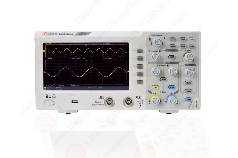
Engineers who test and debug electrical circuitry rely heavily on digital. With their help, electrical waveforms may be captured and visualized for in-depth examination and troubleshooting. The importance of digital oscilloscopes in the testing and troubleshooting of electrical circuits will be discussed in detail.
We’ll go into detail about a wide range of topics, including how engineers may use tools like waveform observation, signal analysis, time-domain measurements, trigger capabilities, and advanced features to spot and fix circuit problems.
Engineers may optimize their design and development processes and attain peak circuit performance by familiarizing themselves with the features of digital oscilloscopes in testing and debugging.
Waveform Observation and Visualization
Engineers may use digital oscilloscopes to monitor and display waveforms in real time in order to better understand the behavior of electrical signals. This may be done in order to better understand how electrical signals behave. Engineers are able to capture and examine voltage waveforms at a variety of points within the circuit by using the probes on the oscilloscope.
The high-resolution displays used in digital oscilloscopes make it simple to analyze the voltage, frequency, and amplitude, along with any other waveform properties, with pinpoint precision. Visual examination of the waveforms may be performed by the engineers in order to look for irregularities such as noise, distortion, glitches, or unusual signal fluctuations.
The ability to visualize the waveform is essential for gaining an understanding of the functioning of the circuit and locating any issues that may exist.
Signal Analysis and Measurements
When attempting to identify the cause of a faulty circuit, engineers may find that the broad signal processing and measurement capabilities of digital oscilloscopes are of great assistance. These devices may capture a wide variety of parameters, including voltage, intervals, rise and fall times, pulse width, and frequency, to name a few of the more common ones.
Because of these features, engineers are able to objectively compare the performance of circuits to the requirements of the design. Engineers are able to examine the frequency content of signals and find harmonics or noise components by using the Fast Fourier Transform (FFT) function of a digital oscilloscope in conjunction with other complex mathematical procedures.
Other analytical tools, such as waveform math operations, which enable engineers to carry out mathematical calculations on collected waveforms, may also be used by engineers in the course of additional analysis and troubleshooting. These activities may be carried out.
Time-Domain Measurements and Characterization
Measurements taken in the time domain by a digital oscilloscope are necessary in order to get a complete comprehension of the timing and behavior of a signal. Digital oscilloscopes may be used by engineers in order to estimate rise and fall times, measure time intervals, and evaluate the latency associated with signal transmission. By using these time-domain measures, issues such as signal distortion, poor timing, and a lack of synchronization may potentially be identified and remedied. Using a comparison of the actual waveforms with the expected waveforms, engineers may ensure that a circuit is operating correctly.
Time-domain measurements are the only way to guarantee accurate timing and maintain signal integrity in high-speed digital circuits, two requirements that must be met simultaneously.
Triggering Capabilities for Capturing Specific Events
Because the digital oscilloscope has so many different triggering mechanisms, engineers are able to capture specific events or anomalies that occur inside the circuit. LISUN has a wide variety of oscilloscopes.
Engineers may utilize triggers to hone down on the important aspects of the waveform and disregard the unimportant aspects of the waveform. Engineers may utilize a wide range of voltage levels, pulse lengths, edge transitions, and signal patterns as triggers for event collecting and analysis. These triggers can be employed in a number of different ways.
This capability is especially helpful when dealing with complex or intermittent signal anomalies. If engineers have a detailed record of the necessary waveform segments, it allows them to examine and troubleshoot problematic areas of a circuit in a circuit more quickly and effectively.
Advanced Features for In-Depth Analysis
The testing and troubleshooting operations are made much easier by the complex capabilities that are included into digital oscilloscopes. These skills enable the analysis of digital communication signals such as I2C, SPI, UART, and CAN bus, and they offer advanced triggering options such as serial triggering and protocol decoding.
In addition, these capabilities enable the study of digital communication signals. Using serial triggering and decoding, which is helpful for debugging and troubleshooting digital interfaces, engineers may investigate the communication protocols that are used between the various components of the circuit.
On certain digital oscilloscopes, you may access more advanced measurement functions like as automated measurements, mask testing, and waveform math operations. Utilizing automated measurements that offer consistent readings on regularly measured parameters may help engineers save time and reduce the likelihood of making errors in their work.
When doing mask testing, engineers compare the signals they have collected to predetermined masks or limits in order to determine whether or not the signals fall within the allowed ranges. Waveform math operations provide engineers with the ability to do mathematical calculations on a variety of waveforms, which in turn enables the engineers to conduct more in-depth analyses and troubleshooting.
Debugging Complex Systems and Interactions
Debugging complicated systems and learning how its parts work together is where digital oscilloscopes really shine. Multiple interdependent subsystems and integrated circuits in contemporary electrical circuits make it difficult to isolate and fix malfunctions. Engineers are able to examine and compare waveforms from different parts of the circuit in real time with the help of digital oscilloscopes that provide numerous input channels.
Timing problems, signal interactions, and possible cross-talk between components may all be isolated using this feature. Engineers can pinpoint the origins of issues by studying the synchronized waveforms in detail.
Remote Monitoring and Collaborative Debugging
Engineers can work together more effectively on debugging and troubleshooting issues when using a digital oscilloscope that supports remote monitoring. Remote monitoring enables engineers to see waveforms, take measurements, and tweak parameters without being physically present at the circuit under test.
This feature is particularly useful when a project calls for the participation of specialists or teams situated in various parts of the world. Efficiency is increased, travel expenses are decreased, and real-time communication amongst engineers is made possible via remote monitoring and collaborative debugging.
Documentation and Reporting
Features included into digital oscilloscopes allow for the recording, storage, and documentation of measured values and waveforms. Engineers may record waveforms, take screenshots, and save measurement data for later use.
This feature is helpful for documenting the debugging procedure, presenting findings, and facilitating knowledge transfer. In addition, some digital oscilloscopes provide sophisticated data management features that let engineers store, retrieve, and compare captured data.
Conclusion
The use of a digital oscilloscope makes it much simpler to test and troubleshoot electrical circuits because it enables exact observation of waveforms, signal analysis, time-domain measurements, triggering capabilities, and other advanced features for in-depth analysis. This makes it possible to detect and eliminate problems more quickly.
By capturing, displaying, and analyzing electrical data, engineers are able to identify irregularities, diagnose problems, and improve the performance of circuits. As a result of the increasing complexity of electrical systems, engineers working in a variety of industries are increasingly reliant on digital oscilloscopes.
When testing and debugging electrical circuits, engineers that use digital oscilloscopes may find that they may save time and effort while also enhancing the quality of the circuits and their operation.
Lisun Instruments Limited was found by LISUN GROUP in 2003. LISUN quality system has been strictly certified by ISO9001:2015. As a CIE Membership, LISUN products are designed based on CIE, IEC and other international or national standards. All products passed CE certificate and authenticated by the third party lab.
Our main products are Goniophotometer, Integrating Sphere, Spectroradiometer, Surge Generator, ESD Simulator Guns, EMI Receiver, EMC Test Equipment, Electrical Safety Tester, Environmental Chamber, Temperature Chamber, Climate Chamber, Thermal Chamber, Salt Spray Test, Dust Test Chamber, Waterproof Test, RoHS Test (EDXRF), Glow Wire Test and Needle Flame Test.
Please feel free to contact us if you need any support.
Tech Dep: [email protected], Cell/WhatsApp:+8615317907381
Sales Dep: [email protected], Cell/WhatsApp:+8618117273997

 中文简体
中文简体