LM-79 Moving Detector Goniophotometer (Mirror Type C)
LSG-6000

High Precision Rotation Luminaire Goniophotometer
LSG-1890B

High Precision Rotation Luminaire Goniospectroradiometer
LSG-1890BCCD

Goniophotometer for Automotive and Signal Lamps
LSG-1950

Goniophotometer for Traffic Signal Lamps (Economical Model)
LSG-1950S

VAD Fire Alarm Visual Alert Device Goniophotometer
LSG-1930
Goniophotometer for Airfield Lighting
LSG-1940

Compact Goniophotometer
LSG-1200A

LED Goniophotometer
LSG-1100
Near Field Moving Detector Goniophotometer
LSG-1900B
 LEDs and Luminaire Test Solutions
 LM-79 and LM-80 Test Solutions
 LED Driver Test Solutions
 Household Appliances Test Solutions
 Mobile and Network Test Solutions
 Automotive Electronics Test Solutions
 Audio-Video and IT Test Solutions
 Cable and Wire Test Solutions
 Plugs and Sockets Test Solutions
 Power Switch Test Solutions
 Transformer Test Solutions
 Electric Toys Test Solutions
 Energy Meter Test Solutions
 Motor-Operated Tool Test Solutions
Select an organization
to browse standards
Abstract
In the actual operating environment of electrical and electronic equipment, spatial radio‑frequency electromagnetic fields couple through power cables and various signal cables to generate conducted disturbance signals, which may result in abnormal operation, functional failure or even hardware damage of equipment. IEC 61000‑4‑6 and its Chinese equivalent standard GB/T 17626.6‑2017 specify test methods for immunity to conducted disturbances induced by radio‑frequency fields. The RF Conducted Immunity Test System serves as the core test equipment for this electromagnetic compatibility verification. This paper discusses the LISUN RFCI61000‑6 RF Conducted Immunity Test System, introduces its working principle, hardware architecture and three standard injection methods, compares key parameters of equipment with different power ratings, analyzes equipment selection logic and practical applications in lighting, medical treatment, industrial control, new energy and other industries. It provides references for laboratories to carry out compliance tests in accordance with IEC 61000‑4‑6.
Modern electrical and electronic devices are generally equipped with long power cords and communication signal cables. Under the effect of spatial radio‑frequency electromagnetic fields, cables can induce RF conducted interference voltages. Such interference enters the internal circuits of equipment under test along cables and imposes impacts on analog signals, digital communication and power supply loops, causing various faults such as communication interruption, garbled display and disordered control logic. To uniformly evaluate equipment immunity against such interference, the International Electrotechnical Commission has released the IEC 61000‑4‑6 standard, and the corresponding domestic standard is GB/T 17626.6‑2017. The standard covers the test frequency range from 150 kHz to 230 MHz, and defines three standardized disturbance injection approaches: CDN method, electromagnetic clamp method and current clamp method. All devices requiring EMC certification shall complete this immunity test. The RF Conducted Immunity Test System can reproduce conducted disturbances induced by real‑world radio‑frequency fields, and it is an essential hardware platform for laboratories to perform such tests.
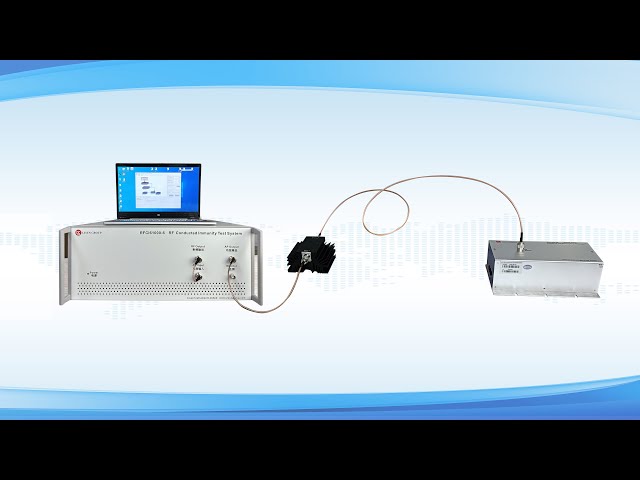
Traditional test solutions for RF conducted immunity are mostly built by stacking multiple instruments including signal generators, external power amplifiers and external power meters. Complex wiring between instruments leads to cumbersome calibration and debugging procedures, and high professional requirements for test operators. The LISUN RFCI61000‑6 RF Conducted Immunity Test System is optimized in hardware architecture. It integrates three core modules: signal generator, power amplifier and power meter inside one main unit, reducing signal loss caused by RF cable connections among separate instruments. The device is equipped with a Chinese‑English Android touch screen to simplify parameter configuration and test procedures. The main unit can cooperate with supporting coupling‑decoupling networks, electromagnetic injection clamps and current injection clamps to finish test tasks for different cable types.
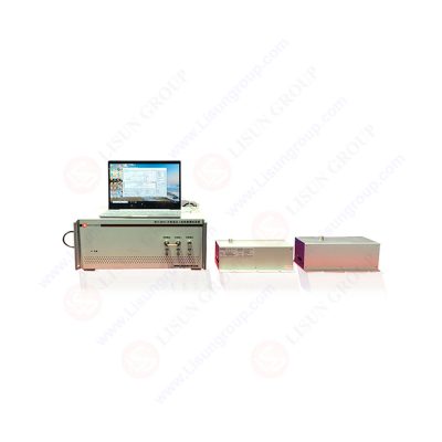
RFCI61000-6_RF Conducted Immunity Test System RFCI61000 6
The core function of the RF Conducted Immunity Test System is to simulate conducted disturbance signals induced by radio‑frequency fields. Standardized injection approaches are adopted to apply disturbance onto power lines and signal lines of the equipment under test, so as to assess the operational stability of equipment under such RF conducted interference. According to requirements of IEC 61000‑4‑6, test engineers shall select appropriate injection methods considering cable type, cable quantity and operating current of the equipment under test. The three mainstream injection methods are CDN method, electromagnetic clamp method and current clamp method.
The CDN method, also known as coupling‑decoupling network injection, is the preferred test method specified in standards. The coupling‑decoupling network couples RF disturbance signals to test cables on one hand, and isolates RF signals from external circuits on the other hand to prevent external circuits from interfering with test results. CDNs include multiple variants for power lines, balanced signal lines, unbalanced signal lines and shielded lines, which are suitable for single‑phase / three‑phase power cables as well as communication cables such as RJ45 and USB. The electromagnetic clamp method applies to multi‑core cables where CDNs cannot be conveniently deployed. It injects RF energy via magnetic field coupling without electrical disconnection of cables. As another non‑contact coupling solution, the current clamp method targets signal cables with large diameters or special specifications, and is suitable for preliminary troubleshooting and verification of special samples. The main unit of LISUN RFCI61000‑6 RF Conducted Immunity Test System can directly drive the above‑mentioned three types of auxiliary fixtures without extra RF adapters, so it can flexibly satisfy test requirements of various equipment under test.
The LISUN RFCI61000‑6 RF Conducted Immunity Test System has two variants: RFCI61000‑6‑35W and RFCI61000‑6‑85W. Both versions share identical frequency coverage, while they differ in output power and output voltage under different injection approaches. Three independent built‑in power meters are deployed for monitoring, forward power and reverse power measurement respectively. Real‑time RF output monitoring reduces risks of power amplifier overload damage. The system features 50 Ω output impedance with VSWR no higher than 1.2 to guarantee stable RF output. The internal signal generator supports amplitude modulation and pulse modulation to satisfy modulation signal requirements defined in relevant standards.
| Parameter Category | RFCI61000‑6‑35W | RFCI61000‑6‑85W |
|---|---|---|
| Output Frequency Range | 150kHz~230MHz | 150kHz~230MHz |
| Rated Output Power | 35W | 85W |
| Output Voltage (CDN Method) | 1~17Vrms | 1~30Vrms |
| Output Voltage (Electromagnetic Clamp Method) | 1~11Vrms | 1~18Vrms |
| Output Voltage (Current Clamp Method) | N/A | 1~10Vrms |
| System Output Impedance | 50Ω (±5%) | 50Ω (±5%) |
| Voltage Standing‑Wave Ratio (VSWR) | ≤1.2 | ≤1.2 |
| Built‑in Signal Generator Frequency Range | 9kHz~1GHz | 9kHz~1GHz |
| Harmonic Suppression | <15dBc | <15dBc |
Complete tests cannot be accomplished merely with the main unit of the RF Conducted Immunity Test System. Corresponding auxiliary fixtures shall be selected according to cable conditions of samples under test. For single‑phase or three‑phase powered equipment, power‑line CDNs with matching current ratings should be adopted. For communication signal cables such as RJ45 and USB, signal‑line‑oriented CDNs are required. For samples with complex or special‑specification wire harnesses, AB‑EM electromagnetic injection clamp or AB‑100W current injection clamp can be used for testing. All CDN fixtures need to cooperate with CDN‑CS100 calibration jigs for periodic calibration to ensure test accuracy.
The RF Conducted Immunity Test System is widely applied in EMC compliance tests for lighting equipment, medical devices, power apparatus, industrial controllers, new‑energy charging piles, communication equipment and other products. Enterprises can use this system for preliminary immunity troubleshooting during research and development phases to detect hardware design defects in advance. Third‑party testing laboratories utilize this equipment for compliance assessment and generate corresponding test records. The integrated main‑unit architecture lowers debugging thresholds, so in‑house laboratories of enterprises can rapidly build test environments complying with IEC 61000‑4‑6.
IEC 61000‑4‑6 is a critical test item for electromagnetic compatibility assessment of electrical and electronic products, and the RF Conducted Immunity Test System is the core equipment for this test. The LISUN RFCI61000‑6 RF Conducted Immunity Test System adopts an integrated design integrating signal generator, power amplifier and power meter. It supports three standard injection solutions including CDN method, electromagnetic clamp method and current clamp method for immunity tests on power lines and various signal lines. During practical equipment selection, users shall determine power rating of the main unit and supporting fixtures based on test voltage requirements and cable types defined in product standards. Proper configuration of the complete test setup can effectively perform RF conducted immunity verification, help products meet international and domestic EMC requirements, and improve operational stability of electronic products in complex radio‑frequency electromagnetic environments.
Tags:RFCI61000-6Your email address will not be published. Required fields are marked *

 English
 中文简体
中文简体 English
 Русский
 Español
 Português
 Türkçe
 العربية
 Deutsch
 Polski
 Italiano
 Français
 한국어
한국어 ไทย
ไทย Tiếng Việt
 日本語
日本語