LM-79 Moving Detector Goniophotometer (Mirror Type C)
LSG-6000

High Precision Rotation Luminaire Goniophotometer
LSG-1890B

High Precision Rotation Luminaire Goniospectroradiometer
LSG-1890BCCD

Goniophotometer for Automotive and Signal Lamps
LSG-1950

Goniophotometer for Traffic Signal Lamps (Economical Model)
LSG-1950S
Goniophotometer for Airfield Lighting
LSG-1940

VAD Fire Alarm Visual Alert Device Goniophotometer
LSG-1930

Compact Goniophotometer
LSG-1200A

LED Goniophotometer
LSG-1100
Near Field Moving Detector Goniophotometer
LSG-1900B
 LEDs and Luminaire Test Solutions
 LM-79 and LM-80 Test Solutions
 LED Driver Test Solutions
 Household Appliances Test Solutions
 Mobile and Network Test Solutions
 Automotive Electronics Test Solutions
 Audio-Video and IT Test Solutions
 Cable and Wire Test Solutions
 Plugs and Sockets Test Solutions
 Power Switch Test Solutions
 Transformer Test Solutions
 Electric Toys Test Solutions
 Energy Meter Test Solutions
 Motor-Operated Tool Test Solutions
Select an organization
to browse standards
Abstract|
In industrial environments, frequent grid switching, relay contact bouncing and on‑off operations of inductive loads generate massive high‑frequency electrical fast transient burst disturbances. Such interference may easily trigger communication interruption, program runaway, system crash or reset on industrial control equipment and instruments. An EFT Immunity Test System serves as the core hardware to reproduce this type of electromagnetic interference and perform EMC immunity evaluation. The electrical fast transient burst generator is a high‑precision device specially designed for electromagnetic compatibility (EMC) immunity testing. Its core function is to simulate high‑frequency pulses generated by real‑world disturbances such as grid switching operations and relay contact bouncing that electrical and electronic equipment may encounter during operation. It is adopted to evaluate the immunity performance of equipment against such interference and guarantee stable operation even in complex electromagnetic environments. Based on the standard requirements for an EFT Immunity Test System and the product features of the LISUN EFT61000‑4 EFT Immunity Test System, this paper carries out model‑selection analysis from multiple dimensions including waveform specifications, coupling‑decoupling networks and supporting accessories, providing references for manufacturers, R&D laboratories and third‑party testing institutions to select a qualified EFT Immunity Test System.
With the continuous improvement of industrial automation, a large number of inductive loads such as frequency converters, contactors and relays are frequently started and stopped on‑site. Transient bursts of repetitive high‑frequency pulses, known as electrical fast transients, are produced the moment these loads switch on or off. Although the energy of individual pulses is limited, dense high‑frequency pulse bursts can severely affect digital circuits and communication interfaces. Many devices run perfectly under ideal laboratory conditions but behave abnormally after field installation. A major root cause is insufficient EFT immunity verification without a qualified EFT Immunity Test System.
According to GB/T 17626.4‑2018 and IEC/EN 61000‑4‑4, products must pass electrical fast transient burst immunity testing before market release. An EFT Immunity Test System can reproduce real‑world burst interference under laboratory conditions and complete pre‑compliance verification at the R&D stage to expose defects in hardware protection, PCB layout and grounding design. Different suppliers deliver EFT Immunity Test System with distinct configurations. Many purchasers only focus on the maximum output voltage while ignoring critical indicators such as pulse rise time, pulse width, rated current of coupling‑decoupling networks and test accessories. This may result in distorted test results that fail to reflect the real anti‑interference performance of equipment, and even lead to pre‑compliance pass but formal certification failure. A thorough understanding of standard specifications and proper selection of an EFT Immunity Test System is critical for industrial EMC compliance.
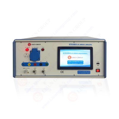
EFT61000-4_EFT Immunity Measurement
GB/T 17626.4‑2018 is the Chinese equivalent of the international standard IEC 61000‑4‑4, which defines mandatory specifications for an EFT Immunity Test System, including pulse waveform parameters, output impedance, pulse repetition frequency, burst duration and burst period. The standard specifies a pulse rise time of 5 ns ±30 %, a pulse width of 50 ns ±30 % under a 50 Ω load, two levels of output impedance (50 Ω and 1000 Ω), and an adjustable pulse frequency ranging from 1 kHz to 1000 kHz. Interference is delivered in burst mode with configurable burst length, burst period and selectable polarities: positive, negative and alternating polarity.
A coupling‑decoupling network is an indispensable component of a complete EFT Immunity Test System. For power line testing, the coupling‑decoupling network injects burst interference into the power supply circuit of the equipment under test while preventing pulse energy from flowing back to the external mains supply. The rated operating current of the coupling‑decoupling network must exceed the maximum working current of the device under test. For communication signal lines such as RJ45 and RS485, a capacitive coupling clamp is required to inject EFT bursts onto signal cables rather than a power‑supply‑oriented coupling‑decoupling network. In addition, dedicated calibration kits are required to periodically verify pulse waveforms for long‑term measurement accuracy. A standalone pulse generator without the above supporting components cannot perform a full‑standard electrical fast transient burst immunity test.
The LISUN EFT61000‑4 EFT Immunity Test System fully complies with GB/T 17626.4‑2018 and IEC/EN 61000‑4‑4 standards. Equipped with a bilingual Android touchscreen and pre‑installed standard test routines, the system supports one‑click recall of IEC‑defined test levels. The series consists of multiple variants differentiated by maximum output voltage and rated current of coupling‑decoupling networks, covering test requirements from low‑power consumer electronics to high‑power industrial equipment. Some models integrate built‑in three‑phase five‑wire coupling‑decoupling networks, while high‑current versions adopt external high‑power units. The complete EFT Immunity Test System can be optionally equipped with the EFT‑CLAMP capacitive coupling clamp for signal‑line testing, the EFT‑CAL calibration kit for waveform verification and the EFT‑DESK standard test bench to build a fully compliant test environment. Key parameters of the main EFT61000‑4 models are listed in the table below.
| Technical Parameter | EFT61000‑4 | EFT61000‑4A | EFT61000‑4‑32A | EFT61000‑4A‑32A | EFT61000‑4‑100A | EFT61000‑4A‑100A |
|---|---|---|---|---|---|---|
| Output Voltage | 0~5kV | 0~6kV | 0~5kV | 0~6kV | 0~5kV | 0~6kV |
| Pulse Rise Time | 5ns±30% | 5ns±30% | 5ns±30% | 5ns±30% | 5ns±30% | 5ns±30% |
| Output Impedance | 50Ω, 1000Ω | 50Ω, 1000Ω | 50Ω, 1000Ω | 50Ω, 1000Ω | 50Ω, 1000Ω | 50Ω, 1000Ω |
| Pulse Frequency | 1kHz‑1000kHz | 1kHz‑1000kHz | 1kHz‑1000kHz | 1kHz‑1000kHz | 1kHz‑1000kHz | 1kHz‑1000kHz |
| Coupling‑Decoupling Network | Built‑in 16A 3‑Phase 5‑Wire | Built‑in 16A 3‑Phase 5‑Wire | Built‑in 32A 3‑Phase 5‑Wire | Built‑in 32A 3‑Phase 5‑Wire | External 100A 3‑Phase 5‑Wire | External 100A 3‑Phase 5‑Wire |
| Pulse Polarity | Positive / Negative / Alternating | Positive / Negative / Alternating | Positive / Negative / Alternating | Positive / Negative / Alternating | Positive / Negative / Alternating | Positive / Negative / Alternating |
EFT61000‑4 and EFT61000‑4A are equipped with built‑in 16A coupling‑decoupling networks for low‑power consumer electronics and medium‑sized industrial control modules. EFT61000‑4‑32A and EFT61000‑4A‑32A integrate a 32A three‑phase five‑wire coupling‑decoupling network for industrial devices with higher operating current. EFT61000‑4‑100A and EFT61000‑4A‑100A adopt an external 100A high‑power coupling‑decoupling network specially for high‑power industrial controllers and power supplies. If the equipment under test contains communication cables such as Ethernet or RS485, the optional EFT‑CLAMP capacitive coupling clamp is required to perform EFT immunity testing on signal lines. The EFT‑CAL calibration kit can verify pulse rise time and pulse width periodically to guarantee long‑term measurement precision of the EFT Immunity Test System.
Enterprises and laboratories shall evaluate an EFT Immunity Test System from multiple dimensions instead of only comparing the maximum output voltage. First, confirm the complete EFT Immunity Test System complies with GB/T 17626.4‑2018 and IEC 61000‑4‑4, verify critical waveform parameters including pulse rise time and pulse width, and check valid calibration certificates. Second, ensure the rated current of the coupling‑decoupling network exceeds the maximum operating current of the device under test. Low‑current built‑in CDNs apply to low‑power prototypes, while high‑power industrial equipment requires 32 A or even 100 A‑grade coupling‑decoupling networks.
Third, distinguish test objects. If the product is fitted with communication signal cables, confirm whether a capacitive coupling clamp is supplied or available as an optional accessory for signal‑line burst immunity testing. Fourth, evaluate instrument functionality. Full functions such as pulse polarity switching, adjustable pulse frequency, burst duration and test duration must be supported, and a touch‑based human‑machine interface improves testing efficiency. Fifth, consider supporting accessories. Calibration kits and standard test benches are essential long‑term laboratory assets. Safety protection measures shall also be taken into account for high‑voltage EMC testing. Finally, assess the supplier’s technical service capacity, including equipment maintenance, metrology guidance, standard interpretation and test technical support, to ensure the EFT Immunity Test System can operate reliably over its service life.
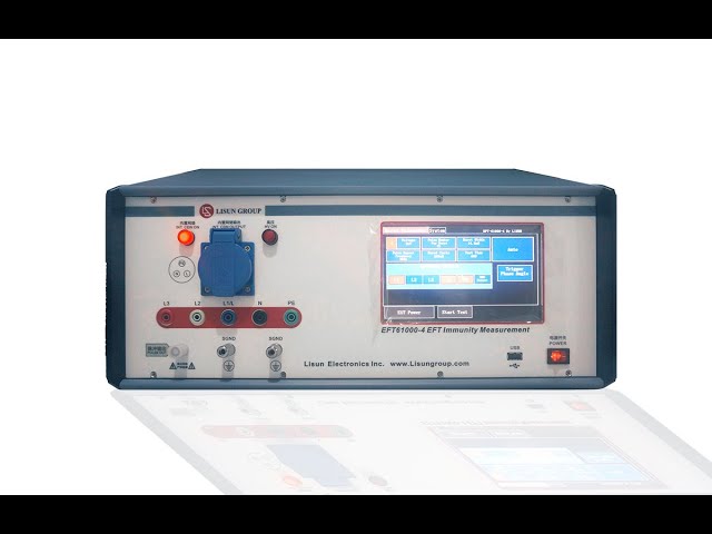
Within industrial control sectors, the LISUN EFT61000‑4 EFT Immunity Test System is used for pre‑compliance immunity verification of PLCs, frequency converters, industrial gateways and sensor modules. It reproduces burst interference triggered by relay and contactor operations and monitors whether devices suffer communication dropout or false output, guiding engineers to optimize power filter circuits, cable shielding and PCB layouts. In consumer electronics and home appliance industries, this EFT Immunity Test System verifies adapters and smart home controllers to identify weak points on power ports in advance and reduce certification failure risks. In the medical device sector, EFT immunity validation is performed in accordance with medical EMC standards to guarantee equipment reliability.
Third‑party testing laboratories deploy the EFT Immunity Test System for formal certification tests to generate compliant test data supporting CE, CB and other international approvals. Developers shall note that pre‑compliance test environments differ from standard laboratory setups. Passing pre‑compliance tests does not guarantee certification approval, and formal sample submission shall still follow standard procedures.
An EFT Immunity Test System is indispensable equipment for industrial EMC compliance testing. The electrical fast transient burst generator is a high‑precision device specially designed for electromagnetic compatibility (EMC) immunity testing. Its core function is to simulate high‑frequency pulses generated by real‑world disturbances such as grid switching operations and relay contact bouncing that electrical and electronic equipment may encounter during operation. It is adopted to evaluate the immunity performance of equipment against such interference and guarantee stable operation even in complex electromagnetic environments. The LISUN EFT61000‑4 EFT Immunity Test System provides diversified configurations covering low‑power consumer electronics as well as high‑power industrial machinery. When selecting equipment, laboratories and manufacturers shall choose appropriate models based on the operating current of the device under test, test voltage levels and signal‑line testing requirements. Importance shall be attached to supporting devices such as coupling‑decoupling networks and calibration kits, and periodic metrological verification shall be carried out to maintain test accuracy, helping all types of electrical and electronic products achieve industrial EMC compliance certification.
Tags:EFT61000-4Your email address will not be published. Required fields are marked *

 English
 中文简体
中文简体 English
 Русский
 Español
 Português
 Türkçe
 العربية
 Deutsch
 Polski
 Italiano
 Français
 한국어
한국어 ไทย
ไทย Tiếng Việt
 日本語
日本語