LM-79 Moving Detector Goniophotometer (Mirror Type C)
LSG-6000

High Precision Rotation Luminaire Goniophotometer
LSG-1890B

High Precision Rotation Luminaire Goniospectroradiometer
LSG-1890BCCD

Goniophotometer for Automotive and Signal Lamps
LSG-1950

Goniophotometer for Traffic Signal Lamps (Economical Model)
LSG-1950S
Goniophotometer for Airfield Lighting
LSG-1940

VAD Fire Alarm Visual Alert Device Goniophotometer
LSG-1930

Compact Goniophotometer
LSG-1200A

LED Goniophotometer
LSG-1100
Near Field Moving Detector Goniophotometer
LSG-1900B
 LEDs and Luminaire Test Solutions
 LM-79 and LM-80 Test Solutions
 LED Driver Test Solutions
 Household Appliances Test Solutions
 Mobile and Network Test Solutions
 Automotive Electronics Test Solutions
 Audio-Video and IT Test Solutions
 Cable and Wire Test Solutions
 Plugs and Sockets Test Solutions
 Power Switch Test Solutions
 Transformer Test Solutions
 Electric Toys Test Solutions
 Energy Meter Test Solutions
 Motor-Operated Tool Test Solutions
Select an organization
to browse standards
Abstract
CISPR 16 Compliant 3M Anechoic Chamber serves as the core fundamental site for radiated radio disturbance (EMI) certification tests. Its structure, materials and electrical accessories shall strictly comply with CISPR 16‑1‑4 specifications. Anechoic chambers are divided into two categories: semi‑anechoic chambers and fully‑anechoic chambers. Obvious differences exist between the two types in absorber layout and simulated field environment. By adopting a conductive ground plane to simulate the infinite ground plane of an open‑area test site, semi‑anechoic chambers have become the mainstream test site for EMI tests of consumer electronics and small household appliances. Taking the LISUN AC‑3M 3M semi‑anechoic chamber as the research object , this paper illustrates the overall design logic of CISPR 16 Compliant 3M Anechoic Chamber, analyzes four key design components including shield enclosure, absorbing materials, quiet‑zone dimension and electromechanical supporting system. It compares hardware parameter differences between AC‑3M semi‑anechoic chamber and AC‑3MF fully‑anechoic chamber, sorts out mandatory site acceptance indexes of CISPR 16, and provides complete design references for new construction or renovation of certification‑qualified 3M anechoic chambers for EMC laboratories.
For market access testing of exported and domestic EMC products, radiated radio disturbance RE tests must be performed at standard sites complying with CISPR 16‑1‑4. Restricted by external electromagnetic interference, land occupation and climatic conditions, open‑area test sites cannot stably carry out batch testing for a long time. CISPR‑approved 3M anechoic chambers have become standardized test facilities substituting open‑area test sites. Anechoic chambers fall into two major types: semi‑anechoic chamber and fully‑anechoic chamber. The complete facility consists of two core modules: shielded enclosure and absorbing materials. The shielded enclosure includes shield housing, shield door, ventilation waveguide window, multi‑stage power filter and other protective components. Absorbing materials adopt the combination of ferrite tiles and tapered carbon‑loaded sponge absorbers, which reduce electromagnetic wave reflection to restore the propagation environment of standard test field.
CISPR 16 Compliant 3M Anechoic Chamber imposes rigid acceptance thresholds on internal clear dimension, quiet‑zone diameter, Normalized Site Attenuation (NSA), site voltage standing‑wave ratio and shielding effectiveness. Chamber length, width, height, absorber coverage area and flatness of conductive ground plane will directly affect NSA test results. Out‑of‑spec indexes will lead to failure in CNAS laboratory assessment and invalid product certification reports. LISUN AC‑3M is a standard CISPR 16 Compliant 3M Anechoic Chamber, featuring standardized external housing dimension of 9.5m×6.5m×6.5m and quiet‑zone diameter of 2 meters. Its normalized site attenuation deviation within 30MHz to 1GHz is controlled within ±3.5dB, better than the ±4dB pass threshold specified by CISPR 16. It is suitable for RE radiated emission pre‑compliance and type certification tests of small household appliances, LED devices and small industrial control units. Modular configurations including turntable, antenna tower, independent control room and power amplifier room support customized adjustment according to demands of enterprises and third‑party laboratories.
CISPR 16‑1‑4 defines design boundaries for 3M anechoic chambers from four dimensions: site geometry, shielding protection, absorber system and site verification. All AC‑3M‑type semi‑anechoic chambers for certification testing shall satisfy the following technical constraints simultaneously.
The first requirement relates to site geometry and quiet‑zone design. For 3‑meter test distance, the standard specifies that the effective cylindrical quiet‑zone diameter shall be no less than 2 meters. Electromagnetic wave propagation characteristics at all positions within the quiet zone shall be consistent with an ideal open‑area test site. The external housing dimension shall reserve installation space for absorbers, turntable and antenna tower. Insufficient housing size will bring wall absorbers too close to the quiet zone, and high‑frequency reflected signals will interfere with receiver readings. Semi‑anechoic chambers install absorbers on five surfaces while retaining a continuous conductive ground plane to simulate ground reflection path of open‑area test sites. Fully‑anechoic chambers deploy absorbers on all six surfaces for free‑space tests without ground plane. Structural differences determine applicable test items. Only semi‑anechoic chambers are accepted by CISPR 16 for EMI radiated emission tests.
The second requirement is shielding system specification. The standard requires full‑band shielding effectiveness to reach defined thresholds: magnetic field attenuation ≥80 dB at 10 kHz, magnetic field ≥100 dB at 100 kHz and above, plane‑wave ≥110 dB at 100 MHz, microwave ≥90 dB at 18 GHz. The shield housing is assembled with prefabricated galvanized steel modules sealed by high‑conductivity mesh gaskets to eliminate electromagnetic leakage at gaps. All cables, power supply and communication lines entering or exiting the chamber shall be connected with corresponding‑grade filters. Honeycomb waveguide windows of 400×400 mm shall be adopted for ventilation to prevent external spurious noise from raising test background noise floor.
The third requirement covers absorber material selection and layout. CISPR 16 demands sufficient electromagnetic wave absorption from 30 MHz to 18 GHz. Ferrite alone works for low‑frequency range while tapered sponge absorbers handle high‑frequency absorption. For LISUN AC‑3M semi‑anechoic chamber, ferrite tiles combined with 300/500 mm EPP absorbers are mounted on walls and ceiling. A 9 m² movable absorber module is reserved on ground for auxiliary absorption of large‑size samples. Absorbers shall achieve flame‑retardant rating UL94 V‑0 and DIN 4102 A2 for fire‑safety consideration. No obvious gaps shall exist between absorber panels, as gaps will produce reflection blind spots and degrade quiet‑zone uniformity.
The fourth requirement concerns site verification indexes, which form the acceptance core of CISPR 16 Compliant 3M Anechoic Chamber. The deviation between measured and theoretical Normalized Site Attenuation (NSA) shall be ≤±4 dB from 30 MHz to 1 GHz; LISUN AC‑3M achieves ±3.5 dB. Site voltage standing‑wave ratio (sVSWR) shall not exceed 5.5 dB from 1 GHz to 18 GHz. Field uniformity for radiated immunity shall be within 0~+6 dB. These three sets of indexes require annual third‑party re‑measurement with reports retained for qualification assessment.
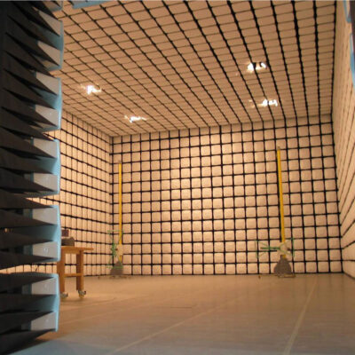
AC- 3M_3m Anechoic Chamber
The complete LISUN AC‑3M semi‑anechoic chamber consists of four major sections: shielded main body, absorber system, electromechanical accessories and auxiliary test partitions. All components cooperate to meet CISPR 16 specifications.
Shielded Enclosure Module
The shield housing adopts prefabricated modular galvanized steel plates. The raised floor provides static load capacity of 1000 kg with seismic resistance grade 8. It is equipped with pneumatic shield door AC‑DR1.5X2P with 1.5 m×2 m opening for regular household appliance access. Ventilation system integrates standard honeycomb waveguide windows. Independent filters are configured for lighting, network, power and communication circuits. N/SMA RF feedthrough panels are installed on walls for leakage‑free connection of receiver and power amplifier RF cables. Internal surveillance cameras can withstand 100 V/m field strength without image distortion caused by electromagnetic interference during testing.
Absorber Layout Scheme
As a CISPR 16 Compliant 3M Anechoic Chamber of semi‑anechoic configuration, AC‑3M does not install fixed absorbers on ground. Five side walls and ceiling are fully covered by composite absorber assemblies. Ferrite tiles are attached to inner shield panels with EPP tapered sponge absorbers mounted outside. Low‑frequency electromagnetic waves are absorbed by ferrite while high‑frequency spurious signals are dissipated by tapered absorbers. Movable ground absorber mats are supplied to reduce superposed ground‑reflection errors when testing tall EUTs, fully complying with open‑area simulation requirements of CISPR 16.
Optional Electromechanical Accessories
Standard configuration includes AC‑TT3M1.5D0.5T test turntable with 1.5 m diameter, 360‑degree continuous rotation and positioning accuracy ±1°. AC‑AT4MS single‑axis 4‑meter motor‑driven antenna tower adjusts antenna height automatically for vertical and horizontal polarization tests. Customers may optionally order independent control room AC‑CT3M and power‑amplifier room AC‑PA3M to isolate receivers, computers and high‑power RF power amplifiers outside the chamber. The power‑amplifier room avoids self‑radiation from amplifiers disturbing quiet‑zone performance and reduces background noise to satisfy low‑noise requirements of CISPR 16.
Compatible Test Instrument System
For CISPR 16 EMI radiated emission tests, R&S ESRP series test receivers, VULB log‑periodic antennas and artificial mains networks can be deployed. For radiated immunity RS tests, LS‑PA series RF power amplifiers, signal generators and field‑strength monitoring probes are adopted. All instruments connect to chamber RF feedthrough panels to perform complete RE and CE certification tests within CISPR 16 Compliant 3M Anechoic Chamber.
Table 1 Parameter Comparison of LISUN 3M / 5M Anechoic Chambers against CISPR 16 Requirements
| Model | Type | External Dimension L*W*H | 3‑meter Test Quiet‑Zone Diameter | Normalized Site Attenuation NSA (30MHz~1GHz) | Site VSWR (1~18GHz) | Absorber Layout | CISPR 16 EMI Compatibility |
|---|---|---|---|---|---|---|---|
| AC‑3M | 3M Semi‑Anechoic Chamber | 9.5*6.5*6.5m | 2.0m | ±3.5dB | ≤5.5dB | Ferrite + EPP absorbers on five surfaces, conductive ground plane | Fully compliant for CISPR 16 RE radiated emission certification test |
| AC‑3MF | 3M Fully‑Anechoic Chamber | 9.5*6.5*6.5m | 2.0m | ±3.5dB | ≤5.5dB | Ferrite + EPP absorbers on all six surfaces | Not applicable for CISPR 16 open‑area‑simulated EMI test |
| AC‑5M | 5M Semi‑Anechoic Chamber | 12.5*8.5*7.5m | 3.0m | ±3.5dB | ≤5.5dB | Ferrite + EPP absorbers on five surfaces, conductive ground plane | Suitable for CISPR 16 RE tests of large‑size equipment |
| AC‑5MF | 5M Fully‑Anechoic Chamber | 12.5*8.5*7.5m | 3.0m | ±3.5dB | ≤5.5dB | Ferrite + EPP absorbers on all six surfaces | Only for free‑space EMS tests |
According to parameter comparison, AC‑3M serves as the only CISPR 16 Compliant 3M Anechoic Chamber. Its semi‑anechoic conductive ground plane reproduces ground reflection paths defined by standards. Fully‑anechoic chambers without ground‑reflection layer cannot be used for CISPR 16 radiated emission type testing. 5‑meter series chambers feature larger quiet zone for automotive and large industrial control equipment, while 3‑meter AC‑3M is preferred for small‑and‑medium‑sized enterprises and small third‑party laboratories developing certification sites for small home appliances, lighting products and power supplies.
Enterprises and test institutions constructing qualified AC‑3M‑type CISPR 16 Compliant 3M Anechoic Chamber shall follow five phases: site survey, structural design, material selection, system configuration and site verification. Each phase shall be implemented in accordance with CISPR 16 clauses.
The first phase is architectural site survey. The chamber shall preferably be located on ground floors, away from external interference sources such as power distribution rooms, motors and RF equipment. Floor foundation load capacity shall be no less than 1000 kg/m². Independent compartments for control room and power‑amplifier room shall be reserved. Door opening dimension shall match maximum EUT outer size. For samples higher than 1.2 m, 2‑meter wide pneumatic shield doors are recommended for unobstructed sample access.
The second phase is shield housing structural design. Steel‑plate thickness and gasket material are determined according to CISPR shielding‑effectiveness targets. Installation positions for waveguide windows, filters and RF feedthrough panels are planned. Power, network and surveillance cables shall be routed separately to avoid spurious coupling which elevates background noise. Special attention shall be paid to sealing of shield joints and door gaps to prevent low‑frequency magnetic‑field leakage.
The third phase is absorber‑system layout design. Absorber height and density on walls and ceiling are calculated based on 2‑meter quiet‑zone diameter for 3‑meter tests. 500‑mm long absorbers are deployed in regions close to quiet zone for improved high‑frequency absorption. High‑density ferrite tiles on lower walls suppress low‑frequency reflection. Storage space for movable ground absorbers is reserved for different‑height EUT testing. Absorber flame‑retardant grades shall comply with laboratory safety regulations referenced by CISPR.
The fourth phase is electromechanical accessory selection. Turntable diameter and antenna‑tower travel are determined by test business. 1.5‑meter turntable meets general small‑home‑appliance requirements. For long‑term batch certification, independent power‑amplifier room is suggested to isolate high‑power RF amplifiers and reduce self‑interference. Power filters shall be configured for single‑phase 32A and three‑phase 32A to cover lighting, instrument and EUT power‑supply branches.
The fifth phase is CISPR 16 site verification. After full installation, third‑party metrology institutes shall perform four measurements: NSA Normalized Site Attenuation, sVSWR site standing‑wave ratio, shielding effectiveness and background noise. The chamber can be put into certification service only when all indexes satisfy standard limits. Full test reports shall be archived for CNAS annual assessment. Re‑verification is mandatory after absorber replacement or shield‑structure modification.
As a qualified CISPR 16 Compliant 3M Anechoic Chamber, LISUN AC‑3M semi‑anechoic chamber covers three mainstream application scenarios: enterprise R&D laboratories, small third‑party test laboratories and quality‑control workshops for lighting and power‑supply manufacturers.
Consumer‑electronics and lighting enterprises deploy AC‑3M in R&D laboratories to conduct pre‑compliance CISPR 16 RE radiated emission tests during product development. Filtering and shielding defects on PCBs can be corrected in advance to improve first‑pass rate for external third‑party certification and shorten new‑product launch cycles. Equipped with compact turntable and single‑axis antenna tower, the chamber occupies moderate footprint and can be flexibly arranged inside factory buildings of small‑and‑medium‑sized manufacturers.
Small third‑party EMC laboratories adopt AC‑3M as their main CISPR 16 Compliant 3M Anechoic Chamber for CE and FCC certification tests of adapters, LED luminaires and small household appliances. The integrated solution with shielding, absorbers, turntable, antenna tower and control room supports one‑time laboratory qualification assessment and delivers internationally‑accepted EMI test reports.
Quality‑control workshops of industrial power‑supply and small medical‑device manufacturers install AC‑3M for sampling radiated‑disturbance inspection on finished goods. Non‑conforming semi‑finished and finished products can be screened out to avoid market‑supervision penalties and recall risks caused by non‑compliant products. Modular construction allows flexible layout orientation matching factory‑space constraints of small‑and‑medium‑size plants.
Designing a 3M semi‑anechoic chamber complying with CISPR standards requires strict implementation of all mandatory requirements specified in CISPR 16‑1‑4 concerning site dimension, shielding effectiveness, absorber layout and NSA site attenuation. The conductive ground plane of semi‑anechoic configuration represents the core design requirement for CISPR 16 EMI radiated emission testing; fully‑anechoic chambers cannot substitute semi‑anechoic chambers for open‑area‑simulated certification tests. LISUN AC‑3M CISPR 16 Compliant 3M Anechoic Chamber meets technical specifications across housing, absorber and electromechanical accessories. Key parameters such as normalized site attenuation and shielding effectiveness exceed standard pass limits. It supports pre‑compliance and type‑certification tests for small home appliances, lighting equipment and compact industrial control devices.
When planning an EMC laboratory anechoic‑chamber project, test institutions and enterprises shall select 3‑meter AC‑3M or 5‑meter semi‑anechoic chambers according to EUT dimensions and business scope. Complete auxiliary components including turntable, antenna tower, independent power‑amplifier room and filter system shall be configured. Four groups of site‑verification measurements defined by CISPR 16 shall be completed after installation to guarantee report admissibility for international certification and provide standardized test environment for EMC compliance evaluation of electronic products for domestic and overseas markets.
Tags:AC-3MYour email address will not be published. Required fields are marked *

 English
 中文简体
中文简体 English
 Русский
 Español
 Português
 Türkçe
 العربية
 Deutsch
 Polski
 Italiano
 Français
 한국어
한국어 ไทย
ไทย Tiếng Việt
 日本語
日本語