LM-79 Moving Detector Goniophotometer (Mirror Type C)
LSG-6000

High Precision Rotation Luminaire Goniophotometer
LSG-1890B

High Precision Rotation Luminaire Goniospectroradiometer
LSG-1890BCCD

Goniophotometer for Automotive and Signal Lamps
LSG-1950

Goniophotometer for Traffic Signal Lamps (Economical Model)
LSG-1950S

VAD Fire Alarm Visual Alert Device Goniophotometer
LSG-1930
Goniophotometer for Airfield Lighting
LSG-1940

Compact Goniophotometer
LSG-1200A

LED Goniophotometer
LSG-1100
Near Field Moving Detector Goniophotometer
LSG-1900B
 LEDs and Luminaire Test Solutions
 LM-79 and LM-80 Test Solutions
 LED Driver Test Solutions
 Household Appliances Test Solutions
 Mobile and Network Test Solutions
 Automotive Electronics Test Solutions
 Audio-Video and IT Test Solutions
 Cable and Wire Test Solutions
 Plugs and Sockets Test Solutions
 Power Switch Test Solutions
 Transformer Test Solutions
 Electric Toys Test Solutions
 Energy Meter Test Solutions
 Motor-Operated Tool Test Solutions
Select an organization
to browse standards
With the continuous iteration of new‑energy and intelligent connected vehicle technologies, the quantity of electronic control units deployed in vehicles keeps increasing. A large number of sensors, domain controllers and on‑board communication modules are densely distributed inside the vehicle. During vehicle operation, motors, ignition systems and various switching devices generate substantial radio‑frequency electromagnetic disturbances. Vehicle wiring harnesses act as receiving antennas and are prone to coupling various radio‑frequency interference currents, which may trigger signal distortion, communication failures and disordered control logic of electronic components. In serious cases, driving safety will be directly jeopardized. To identify electromagnetic compatibility vulnerabilities of on‑board electronic components at an early stage, bulk current injection testing has become an essential verification approach for automotive‑electronic electromagnetic immunity. The Bulk Current Injection Test System is the core hardware platform for performing such tests. This article centers on the LISUN LSBCI‑40 Bulk Current Injection Test System, elaborating its working principle, system composition, test methodologies, evaluation criteria and industry‑oriented application value. For detailed product information.
Basic Principle and Industry Positioning of Bulk Current Injection Test System
The Bulk Current Injection Test System (Bulk Current Injection) is an electromagnetic immunity test equipment developed by LISUN specifically for automotive electronics, rail transit and industrial control sectors. Its core function is to simulate radio‑frequency conducted interference encountered by electronic devices within complex electromagnetic environments. By injecting radio‑frequency current of specified magnitude into the cable harness of the equipment under test, the system assesses the operational stability of electronic devices subject to radio‑frequency interference. It detects functional abnormalities induced by electromagnetic compatibility issues such as signal distortion, bus communication errors and control malfunction in advance, and delivers critical test support for products to pass international EMC certification.
Different from radiated immunity tests conducted inside an anechoic chamber, BCI testing does not expose the equipment under test to spatial radiated fields. Instead, it applies magnetic coupling to directly inject radio‑frequency disturbance current onto the wiring harness of the unit under test, reproducing real‑vehicle common‑mode radio‑frequency interference coupled on vehicle harnesses. Within the EMC standard framework for automotive components, GB/T 33014.4‑2016, ISO 11452‑4:2020 and SAE J1113/4‑2020 specify complete requirements covering BCI test methods, test setup and calibration procedures. BCI has been widely adopted as a mandatory test item for component admission assessments from domestic automobile manufacturers, covering electronic control parts for conventional fuel vehicles, hybrid vehicles and battery electric vehicles.
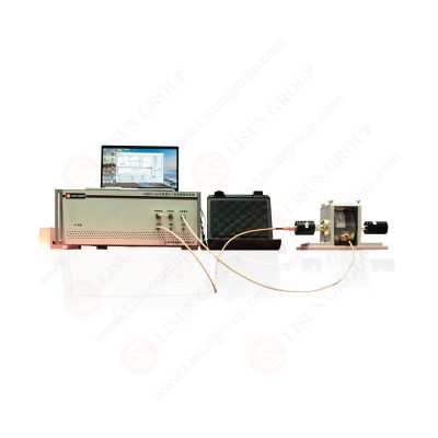
LSBCI-40_Bulk Current Injection Test System
Hardware Configuration and Key Parameters of LSBCI‑40 Bulk Current Injection Test System
The LSBCI‑40 Bulk Current Injection Test System is a fully integrated test unit. Its mainframe incorporates an RF signal generator, linear power amplifier, three‑channel power meter and directional coupler. It is equipped with external test probes, calibration fixtures and artificial mains network, and supports both open‑loop and closed‑loop standard BCI test modes complying with frequency range, modulation modes and test current defined in relevant standards. The table below presents major technical specifications of the LSBCI‑40 Bulk Current Injection Test System.
| Hardware Unit | Key Technical Parameters |
|---|---|
| Test Mainframe | Open‑loop test current ≤300mA; closed‑loop test current ≤200mA; output impedance 50Ω; VSWR ≤1.2; compatible with Win7‑Win11 Chinese‑English test software, featuring full‑automatic calibration and real‑time power monitoring throughout test execution |
| Built‑in Signal Generator | Frequency: 9kHz~3GHz; output level: ‑60~10dBm; supports continuous wave, amplitude modulation 0.1Hz‑500kHz, pulse modulation 0.1Hz‑20kHz |
| Built‑in Power Amplifier | Output frequency: 100kHz‑400MHz, expandable to 1GHz; maximum linear output power 125W; harmonic suppression better than 15dBc |
| Three‑channel Power Meter | Input frequency: 9kHz‑3GHz; measurable power range: ‑40dBm~+30dBm |
| Directional Coupler | Coupling factor 40dB, internally integrated within mainframe |
| Matching Probe Assembly | LIS‑BCP410 injection probe (10kHz‑400MHz); LIS‑BCM410 monitoring probe (maximum pass‑through current 100A); CCF500 calibration fixture; AN100A artificial mains network |
The complete Bulk Current Injection Test System also includes reference ground plane and insulating support brackets. Optional accessories contain dedicated BCI test table and electromagnetic shielding cabinet. Per standard test setup requirements, the reference ground plane shall be brass‑made with thickness above 0.5 mm and ground impedance controlled within 2.5 milliohms. The equipment under test shall be positioned on insulating supports with dielectric constant ≤1.4 and thickness of 50mm±5mm. The total length of test wiring harness shall be kept at 1000mm±100mm as specified by standards. Tests shall be carried out with the injection probe placed at three typical distances of 150 mm, 450 mm and 750 mm away from the equipment under test, to simulate practical interference coupling status at different positions of vehicle wiring harnesses.
Two Test Modes and Test Workflow of Bulk Current Injection Test System
The Bulk Current Injection Test System offers open‑loop method (substitution method) and closed‑loop method. Noticeable differences exist between these two modes in calibration logic and control mechanism. For open‑loop testing, probe calibration shall be completed on calibration fixtures in advance to build the mapping relation between target current and forward output power. During formal testing, pre‑calibrated power parameters are applied for interference injection without real‑time monitoring of radio‑frequency current on wiring harnesses. Frequency sweep testing is performed based on pre‑established power calibration curves. Characterized by fast test speed, the open‑loop mode is mainly used for preliminary R&D evaluation and mass‑production consistency verification of components.
The closed‑loop method deploys extra current‑monitoring probes. Real‑time radio‑frequency current flowing over wiring harnesses is continuously collected during testing. The Bulk Current Injection Test System compares measured current value against preset target current and dynamically adjusts power‑amplifier output, so as to stabilize radio‑frequency current on wiring harnesses at levels required by relevant standards. The closed‑loop mode delivers superior test accuracy and is adopted for strict validation of safety‑critical components, such as vehicle brake control units, steering controllers and autonomous‑driving domain controllers. Whichever test mode is selected, system calibration must be finished before formal testing to eliminate measurement errors introduced by probe loss and cable loss, ensuring repeatable and comparable test results to satisfy certification requirements.
Once testing is finished, operating status of the equipment under test shall be categorized into five grades: Grade A, Grade B, Grade C, Grade D and Grade E. Grade A means all functions and performance remain normal without any anomaly. Grade B represents performance deviation beyond tolerance under interference, with automatic recovery and intact stored data after interference removal. Grade C stands for temporary function loss, and functions can restore automatically after interference disappears. Grade D indicates function loss which demands manual intervention for recovery. Grade E refers to permanent function failure; equipment cannot resume normal operation even after interference is removed. For EMC certification, critical components are generally required to achieve Grade A or Grade B. Grade C, D and E are treated as test failure. Hardware improvement such as adding filter components, optimizing grounding layout and implementing harness shielding shall be conducted before re‑running BCI tests.
Industrial Application Value of Bulk Current Injection Test System
Within the automotive‑electronics industry, the Bulk Current Injection Test System undertakes electromagnetic immunity verification of components, covering engine ECU, body control unit, ADAS domain controller, BMS battery management system, on‑board gateway and other parts. On‑board control equipment for rail transit, as well as PLC and frequency converters from industrial control domain also utilize the Bulk Current Injection Test System for wiring‑harness radio‑frequency immunity validation. Many hardware defects cannot be uncovered under conventional power‑on tests. Latent faults including bus packet loss, signal drift and sporadic reboot can only be reproduced by injecting radio‑frequency interference onto wiring harnesses via BCI. By applying the Bulk Current Injection Test System to expose electromagnetic compatibility defects in the R&D phase, occasional in‑field failures after mass production and vehicle assembly can be avoided, vehicle recall risks are reduced, and reliability and safety of electronic products are enhanced.
From a technical‑testing perspective, the Bulk Current Injection Test System cannot operate independently. It has to cooperate with shielding environment, artificial mains network and equipment‑under‑test status‑monitoring tools to fully meet standard specifications. Driven by high‑voltage trends and domain‑oriented electronic‑architecture evolution of electric vehicles, on‑board wiring harnesses become more complicated, and risks of electromagnetic‑interference coupling on harnesses keep rising. As core equipment for wiring‑harness conducted immunity assessment, the Bulk Current Injection Test System sees growing application demands in product R&D, third‑party testing laboratories and vehicle‑manufacturer component‑qualification projects. Meanwhile, test software functions keep improving. The LSBCI‑40 Bulk Current Injection Test System can automatically complete frequency sweeping, modulation switching and data logging, and directly export test charts, minimizing human‑induced errors and improving overall EMC test efficiency.
Conclusion
Electromagnetic compatibility performance constitutes an indispensable quality metric for modern automotive‑electronic products. Adopting bulk current injection methodology, the Bulk Current Injection Test System simulates real‑world radio‑frequency disturbance coupling on wiring harnesses, and quantitatively evaluates the radio‑frequency conducted anti‑interference performance of electronic devices. As a representative product, the LSBCI‑40 Bulk Current Injection Test System fully complies with domestic and international standards including GB/T 33014.4‑2016 and ISO 11452‑4. It completes immunity testing for automotive electronics, rail transit facilities and industrial‑control devices through open‑loop and closed‑loop test modes, and identifies potential EMC risks in advance. For R&D engineers and testing institutions, comprehensive understanding on principles, hardware parameters, test setup and result‑evaluation criteria of the Bulk Current Injection Test System supports proper test execution and accurate EMC fault localization, thereby providing technical guarantee for safe and stable operation of electronic products.
Your email address will not be published. Required fields are marked *

 English
 中文简体
中文简体 English
 Русский
 Español
 Português
 Türkçe
 العربية
 Deutsch
 Polski
 Italiano
 Français
 한국어
한국어 ไทย
ไทย Tiếng Việt
 日本語
日本語