LM-79 Moving Detector Goniophotometer (Mirror Type C)
LSG-6000

High Precision Rotation Luminaire Goniophotometer
LSG-1890B

High Precision Rotation Luminaire Goniospectroradiometer
LSG-1890BCCD

Goniophotometer for Automotive and Signal Lamps
LSG-1950

Goniophotometer for Traffic Signal Lamps (Economical Model)
LSG-1950S

VAD Fire Alarm Visual Alert Device Goniophotometer
LSG-1930
Goniophotometer for Airfield Lighting
LSG-1940

Compact Goniophotometer
LSG-1200A

LED Goniophotometer
LSG-1100
Near Field Moving Detector Goniophotometer
LSG-1900B
 LEDs and Luminaire Test Solutions
 LM-79 and LM-80 Test Solutions
 LED Driver Test Solutions
 Household Appliances Test Solutions
 Mobile and Network Test Solutions
 Automotive Electronics Test Solutions
 Audio-Video and IT Test Solutions
 Cable and Wire Test Solutions
 Plugs and Sockets Test Solutions
 Power Switch Test Solutions
 Transformer Test Solutions
 Electric Toys Test Solutions
 Energy Meter Test Solutions
 Motor-Operated Tool Test Solutions
Select an organization
to browse standards
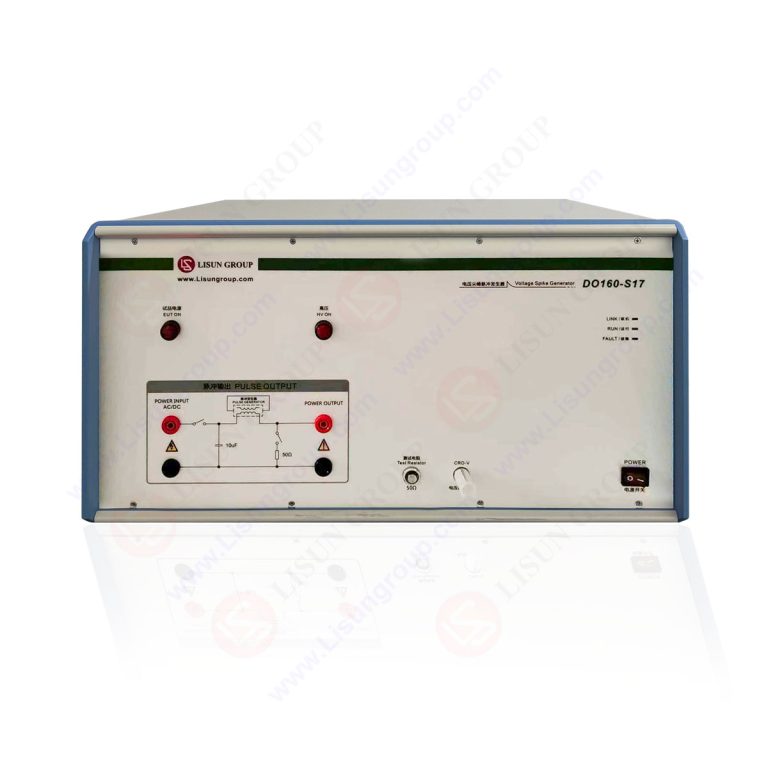
Product No: DO160-S17
DO160-S17 Voltage Spike Generator is designed specifically for voltage spike susceptibility testing on the power ports of airborne equipment. It fully complies with the RTCA DO-160 Section 17 voltage spike test specifications. It is primarily used for voltage spike immunity testing on the AC/DC power inputs of civil aviation airborne equipment and military avionics (in accordance with RTCA DO-160 Section 17), assessing the equipment’s ability to withstand transient spike interference caused by load switching or relay operation on the aircraft’s power bus.
DO160-S17 features a built-in pulse generation unit with a standard 50Ω source impedance, capable of outputting voltage spike waveforms that meet standard definitions (pulse rise time ≤2μs, pulse width 10μs). It applies pulses to the power circuit of the device under test at the repetition rates specified by the standard, accurately replicating the transient spike electromagnetic interference environment found on aircraft power lines. The system supports continuously adjustable pulse amplitude, one-key parameter setup, automatic testing, data storage, and report export.
Note: If you need to perform CS106 testing in accordance with GJB 151A/B/C or MIL-STD-461F to assess the transient spike immunity of AC/DC power ports for surface ship or submarine equipment, please refer to the LIS-CS106-50A Power Line Spike Pulse Generator.
| LISUN Model | DO160-S17 | DO160-S17-50A | DO160-S17-100A |
| Coupling Method | Built-in coupling/decoupling network: Maximum 440V/16A |
External 10 μs coupling transformer: Maximum 440V/50A |
External 10 μs coupling transformer Maximum 440V/100A |
| Test Voltage | 5 V~1000 V (continuously adjustable) | ||
| Ascent Time | ≤2 μs | ||
| Pulse Width | >10 μs | ||
| Impedance | 50 Ω ± 10 % | ||
| Output Polarity | Positive, negative, alternating positive and negative | ||
| Triggering Method | Automatic | ||
DO160-S17 standard waveform diagram and actual waveform diagram
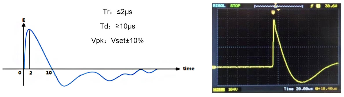
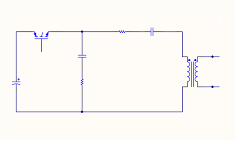
DO160-S17 Schematic Diagram
Introduction Voltage impulse generators, commonly referred to as Voltage Spike Generators, are...
Abstract:Understanding what causes a voltage spike is fundamental to designing robust electronic...
Abstract With the rapid development of electronic and electrical systems, especially in the...

 English
 中文简体
中文简体 English
 Русский
 Español
 Português
 Türkçe
 العربية
 Deutsch
 Polski
 Italiano
 Français
 한국어
한국어 ไทย
ไทย Tiếng Việt
 日本語
日本語