LM-79 Moving Detector Goniophotometer (Mirror Type C)
LSG-6000

High Precision Rotation Luminaire Goniophotometer
LSG-1890B

High Precision Rotation Luminaire Goniospectroradiometer
LSG-1890BCCD

Goniophotometer for Automotive and Signal Lamps
LSG-1950

Goniophotometer for Traffic Signal Lamps
LSG-1950S

Compact Goniophotometer
LSG-1200A

Near Field Moving Detector Goniophotometer
LSG-1900B
Select an organization
to browse standards
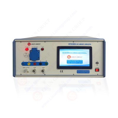
EFT Immunity Measurement is an interference simulation generator for electronic products and is an instrument for the quick transient burst pulse anti-interference test, as well as a kind of electromagnetic compatibility anti-interference test instrument, which is used to testthe resistance of electronic and electrical systems to quick transient interference. This quick transient burst pulse group generator includes power supply system, keyboard unit, display unit, main control unit, high voltage power supply, energy storage capacitor, main capacitor, frequency generating circuit, main switch, waveform circuit and coupling-decoupling circuit. The main control unit controls the high voltage power supply to charge the energy storage capacitor and the energy storage capacitor charges the main capacitor through the charging circuit.

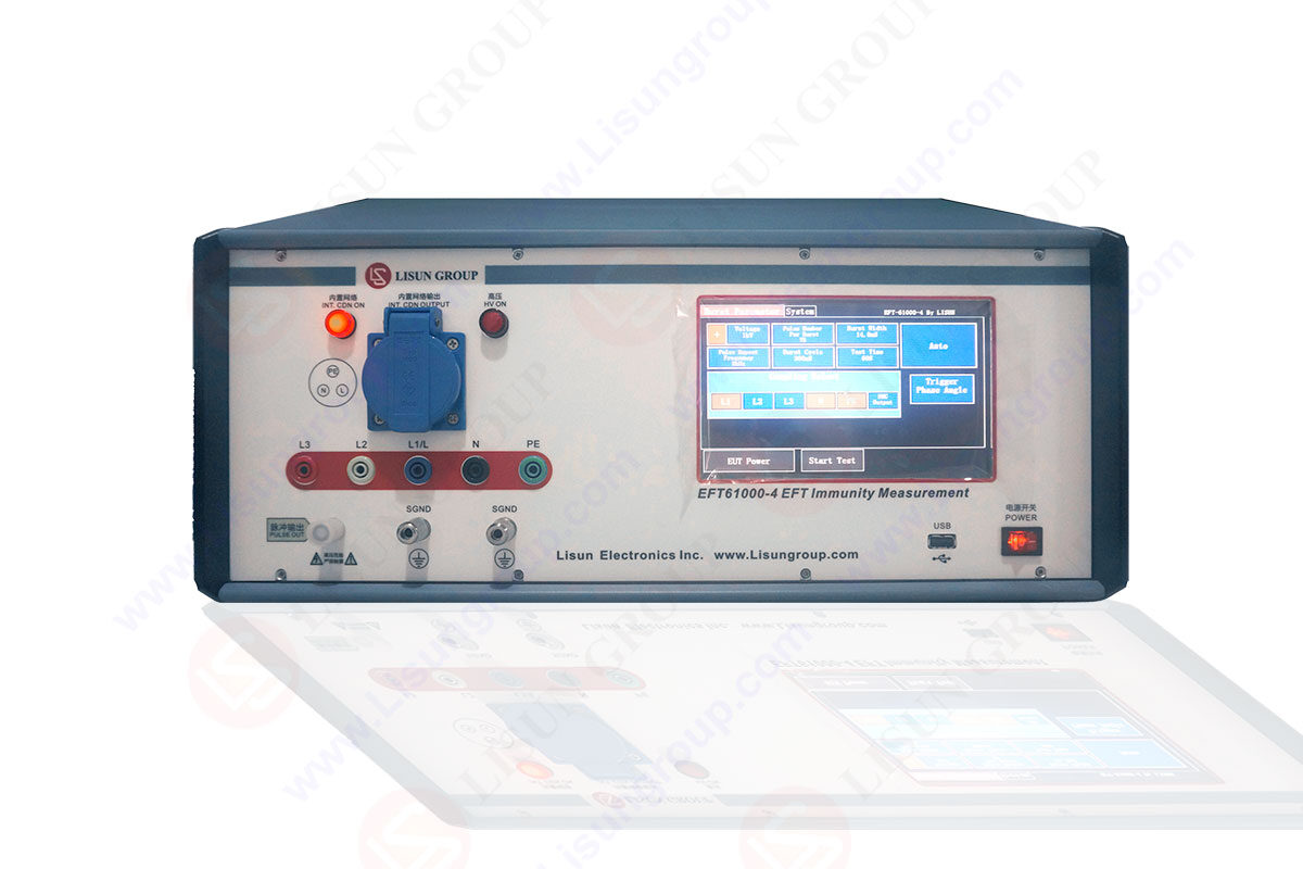
EFT61000-4_EFT Immunity Measurement
The main control unit generates the corresponding control signal according to the preset frequency to control the opening and closing of the main switch. When the main switch is opened, the main capacitor is discharged through the waveform circuit to form the fast transient/burst interference waveform, and the main control unit controls the coupling-decouplingcircuit to couple the interference to the equipment under test (ETU) power supply according to the set channel, or It outputs the interference waveform according to the source output mode. This coupling-decoupling circuit adopts a digital control system, which is easy to operate, has good human-computer interface, shortest coupling path and good waveform consistency. When the main switch is off, the energy storage capacitor is charged to the main capacitor. The frequency generating circuit is used to generate PWM signals to control the main switch. When the switch is switched at different frequencies under the control of different frequency PWM (Pulse Width Modulation) signals generated by the main control unit frequency generating circuit, different frequency quick transient waveforms are generated. Parameters of this generator are input by the keyboard unit and parameter display is completed by the display unit. The power supply system adopts 220V, 50HZ AC power and converts multiple DC power supplies for the generator through the power interface and switch power supply.
A EFT Immunity Measurement, characterized in that it comprises a power supply system, a keyboard unit, a display unit, a main control unit, a high voltage power supply, an energy storage capacitor, a main capacitor, a frequency generating circuit, a main switch, a waveform circuit and a coupling-decoupling circuit, wherein the main control unit controls the high voltage power supply to reach the set voltage and charges the energy storage capacitor, the energy storage capacitor charges the main capacitor through the charging circuit, and the main control unit generates the corresponding control signal according to the preset frequency to control the opening and closing of the main switch When the main switch is opened, the main capacitor forms an interference waveform through the waveform circuit, when the main switch is turned off, the energy storage capacitor is charged to the main capacitor, the frequency generating circuit is used to generate the PWM signal to control the main switch, and When the switch is switched under the control of different frequency PWM signals generated by the main control unitfrequency generating different frequency quick transient waveforms are generated.

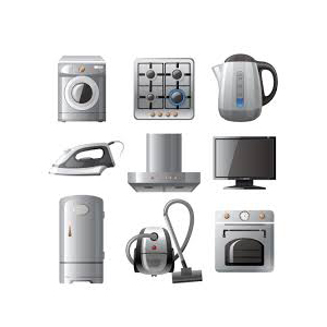
The purpose of the quick transient burst pulse EFT test is to verify the anti-interference ability of mechanical switches caused by inductive load switching, relay contact bouncing, high voltage switch switching and other instantaneous disturbances. This test method is a pulse group test composed of many quick transient pulses coupled to
the power line, control line and signal line. Easy problems occur in power equipment or monitoring power grid equipment, equipment used in industrial automation, medical monitoring and other detection of weak signal equipment.

LISUN’s Motor-Operated Tool | Power Tool Testing solutions strictly comply with a range of core international standards, providing full support for safety and electromagnetic compatibility (EMC)...

LISUN’s electric toy testing solutions cover IEC 62115, EN 71-1, ASTM F963 standards. Including electrical, mechanical, flammability tests to ensure toy safety compliance globally.

LISUN’s transformer test solutions meet IEC 61558-1, IEC 60076-1, IEC 62041 standards. Covering safety, performance, EMC tests, ensuring transformers comply with global requirements.

LISUN’s energy meter testing solutions align with IEC 62052-11, IEC 62053 series standards. Covering safety, electrical, environmental, and EMC tests, we help manufacturers meet global compliance...

LISUN’s household and appliance switch testing solutions meet IEC 60669, IEC 61058, IEC 62271 standards. Covering electrical, mechanical & EMC tests for global compliance.
LISUN has all equipment according to the IEC60669 measurement, including environmental chamber, IP code waterproof dustproof test, switch lift test, etc.

 中文简体
中文简体