
LM-79 Moving Detector Goniophotometer (Mirror Type C)
LSG-6000

High Precision Rotation Luminaire Goniophotometer
LSG-1890B

High Precision Rotation Luminaire Goniospectroradiometer
LSG-1890BCCD

Goniophotometer for Automotive and Signal Lamps
LSG-1950

Goniophotometer for Traffic Signal Lamps
LSG-1950S

Compact Goniophotometer
LSG-1200A

Near Field Moving Detector Goniophotometer
LSG-1900B
Select an organization
to browse standards
Pin entry apertures in socket-outlets shall not exceed the dimensions specified in Table 3.1.
These dimensions shall be checked by measurement. The distance from the cdge of the live pin aperture-
(a) to the extremity of the socket-outlet face or faceplate profile, in Figure 3.2, shall be not less than 11.7 mm, except for 20 A rated socket-outlets, which shall be not less than 10.7 mm; or
NOTE: Within the 10.7 mm and 11.7 mm distance, any radius or shaping of the edges of the faceplate or socket-outlet face needs to be contained within a radius of 2 mm.
(b) to the extremity of the socket-outlet shall not be less than 13.7 mm, and the shaping of the socket-outlet face profile of Figure 3.3, within the 13.7 mm distance specified.
shall not be greater than 3 mm below the plane of the surface surrounding the pin apertures; and
(c) to the nearest point of any metal faceplate shall be not less than 3 mm.
NOTE: Items (a) and (b) need not apply to fully recessed socket-outlet.
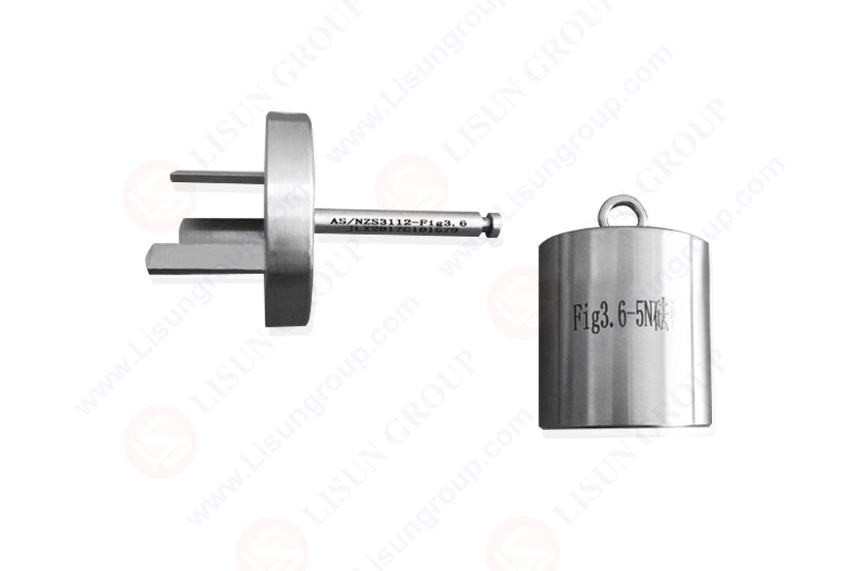
 with AS/NZS 3112 Figure 3.6 5")
GNGPL 3136_AL
Where there is more than one socket-outlet, the centre-to-centre distance between adjacent socket-outlets shall be greater than 44 mm.
 with AS/NZS 3112 Figure 3.6 6")
Device for Checking The Resistance to Lateral Strain (Three-Pin Gauge) with AS/NZS 3112 Figure 3.6
No part of the device, including any switch in any position, shall project more than 8.6 mm from the surface of the socket-outlet face within the shaded arca of Figure 3.4. This requirement applies to all socket-outlets except those with special design features, such as providing protection from dust, wcather or mechanical damage.
There shall be no projections or protrusions greater than 0.5 mm in the arca defined by R21.6 in Figure 3.6.
In case of doubt, to verify projections on the socket face doubt, to verify projections on the socket face do not interfere when a plug or plug in device is inserted, insert the gauge of Appendix D modified as follows: the dimension of the diameter 38 mm is changed to 43.2 mm.
This diameter becomes a raised boss of 8.6 mm to stimulate a plug/plug in device. When inserted the modified gauge shall not interfere with any part of the device or switch.
NOTES:
1. This requirement allows for full insertion of a plug or plug-in device of the size indicated in Figure 2.1 and also prevents inadvertent or partial operation of any switch during insertion.
2. This requirement does not necessarily permit manual operation of any switch with the plug or plug-in device inserted.
3. Examples of projections and protrusions are moulding irregularities and marking.
Where the face of a 10 A, 15 A or 20 A socket-outlet for use with plugs complying with Figure 2.1(c) is fully recessed, the socket-outlet shall comply with Figure 3.5.
Removable portions and breaks in the sidewall of the recess are not permitted. The socket-outlet face and recess sidewall shall form part of the fixed portion of the socket-outlet.
NOTE: This Clause only applics to socket-outlets that are claimed to be fully recessed socket-outlets.
Where an IP-rated socket-outlet has an external thread, the dimensions of the thread shall comply with Figure H1 (b) of Appendix H.The pitch circular dimension (PC) on
the socket shall be as shown in Figure H1(b) of Appendix H.

 中文简体
中文简体