LM-79 Moving Detector Goniophotometer (Mirror Type C)
LSG-6000

High Precision Rotation Luminaire Goniophotometer
LSG-1890B

High Precision Rotation Luminaire Goniospectroradiometer
LSG-1890BCCD

Goniophotometer for Automotive and Signal Lamps
LSG-1950

Goniophotometer for Traffic Signal Lamps
LSG-1950S

Compact Goniophotometer
LSG-1200A

Near Field Moving Detector Goniophotometer
LSG-1900B
Select an organization
to browse standards
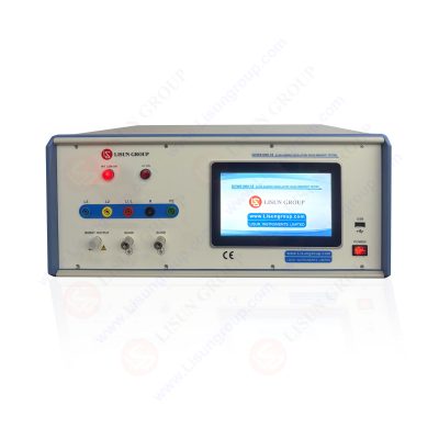
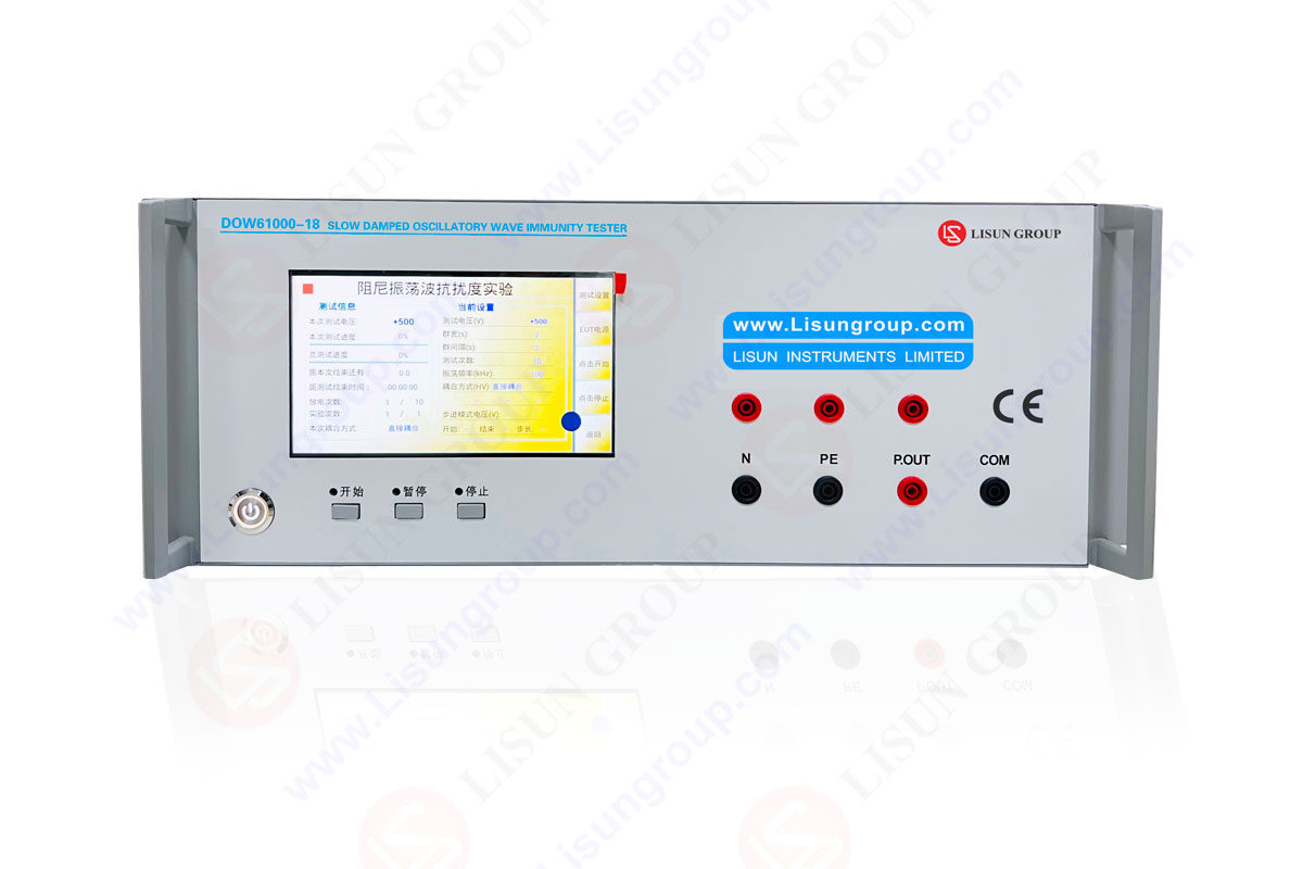
The damped oscillatory wave generator plays a crucial role in assessing the immunity of household, commercial, and industrial electrical equipment to disturbances. This device simulates repetitive damped oscillatory waves on power cables, control cables, and signal cables found in high and medium voltage substations, providing an ideal standard and basis for electromagnetic compatibility (EMC) testing.
Core Components of a Damped Oscillatory Wave Generator:
• High Voltage Source: Provides the necessary voltage.
• Charging Resistor: Controls the current.
• Energy Storage Capacitor: Stores electrical energy, releasing it to generate oscillatory waves.
• High Voltage Switch: Switches the voltage.
• Waveform Network: Forms specific waveforms.
Additionally, the coupling/decoupling network consists of coupling networks and decoupling networks, primarily used for testing AC and DC power supply ports. The capacitive coupling clamp comprises coupling clamps and coaxial connectors at both ends, used for acceptance testing of connections on input, output, and communication ports.

DOW61000 18_Damped Oscillatory Wave Immunity Tester
• Setup: Set the simulator to coaxial output mode and configure the oscilloscope impedance to 50Ω.
• Connection: Connect the simulator to the oscilloscope using connecting cables and attenuators.
• Adjustment: Adjust the oscilloscope to display a complete pulse rise-time waveform in the center of the screen.
• Measurement: Set the oscillation frequencies to 3MHz, 10MHz, and 30MHz respectively, and measure the short-circuit current peak values at different voltage settings.
• Connection: Connect the coupling/decoupling network to the attenuator using a connecting adapter. Ensure the connection between the coupling/decoupling network’s output and the connecting adapter is as short as possible.
• Measurement: Set the oscillation frequencies to 3MHz, 10MHz, and 30MHz respectively, and measure the short-circuit current peak values at different voltage settings.
• Repetition: Change the power line coupling output lines, repeat the above process, and measure the short-circuit current peak values for different coupling lines.
• Setup: Connect the capacitive coupling clamp to the attenuator using a connecting adapter, ensuring good grounding of the adapter.
• Connection: Set the damped oscillatory wave simulator to coaxial mode output with a voltage value of 2kV.
• Adjustment: Set the oscilloscope input impedance to 50Ω and adjust it to display a complete pulse waveform in the center of the screen.
• Measurement: Set the oscillation frequencies to 3MHz, 10MHz, and 30MHz respectively, and measure the open-circuit voltage peak values.
Summary:
The damped oscillatory wave generator is essential for testing the immunity of electrical and electronic devices. Accurate calibration is fundamental to ensuring reliable test results. By systematically calibrating the damped oscillatory wave simulator host, coupling/decoupling network, and capacitive coupling clamp, one can ensure the electromagnetic compatibility of devices across various operational environments.

LISUN’s energy meter testing solutions align with IEC 62052-11, IEC 62053 series standards. Covering safety, electrical, environmental, and EMC tests, we help manufacturers meet global compliance...

LISUN’s household and appliance switch testing solutions meet IEC 60669, IEC 61058, IEC 62271 standards. Covering electrical, mechanical & EMC tests for global compliance.

 中文简体
中文简体