
LM-79 Moving Detector Goniophotometer (Mirror Type C)
LSG-6000

High Precision Rotation Luminaire Goniophotometer
LSG-1890B

High Precision Rotation Luminaire Goniospectroradiometer
LSG-1890BCCD

Goniophotometer for Automotive and Signal Lamps
LSG-1950

Goniophotometer for Traffic Signal Lamps (Economical Model)
LSG-1950S
Goniophotometer for Airfield Lighting
LSG-1940

VAD Fire Alarm Visual Alert Device Goniophotometer
LSG-1930

Compact Goniophotometer
LSG-1200A

LED Goniophotometer
LSG-1100
Near Field Moving Detector Goniophotometer
LSG-1900B
 LEDs and Luminaire Test Solutions
 LM-79 and LM-80 Test Solutions
 LED Driver Test Solutions
 Household Appliances Test Solutions
 Mobile and Network Test Solutions
 Automotive Electronics Test Solutions
 Audio-Video and IT Test Solutions
 Cable and Wire Test Solutions
 Plugs and Sockets Test Solutions
 Power Switch Test Solutions
 Transformer Test Solutions
 Electric Toys Test Solutions
 Energy Meter Test Solutions
 Motor-Operated Tool Test Solutions
Select an organization
to browse standards
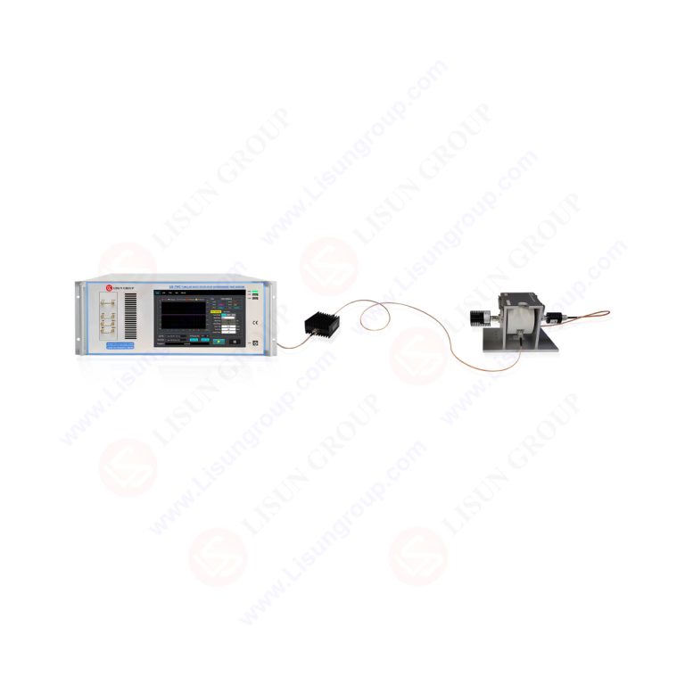
Product No: LIS-TWC-3G50W
LIS-TWC-3G50W Tubular Wave Coupler (TWC) RF Interference Test System is specifically designed for automotive EMC RF immunity testing using the TWC method. It fully complies with automotive EMC standards such as ISO 11452-4, GB/T 33014.4 and SAE J1113-4. The system is primarily used for conducting TWC-based RF conducted and radiated immunity tests (frequency range: 400 MHz to 3 GHz) on various automotive components and electronic devices, making it suitable for R&D pre-compliance testing, product finalization, and third-party laboratory testing.
Featuring an integrated architecture, the LIS-TWC-3G50W has built-in a signal generator, a three-channel high-precision power meter, an RF power amplifier and a dual directional coupler. It supports multiple signal modes—including CW, AM, PM, and unmodulated signals—as well as both average and pulse detection modes, accommodating the requirements of both civilian automotive testing and military pulse testing scenarios. The system includes a comprehensive library of standard tests, supports the loading of standard files and the customization of user-defined test libraries, and features a rapid “one-click” calibration function that completes full-frequency-point calibration in under one minute.
Note: For Bulk Current Injection (BCI) testing method in the 100 kHz to 400 MHz range, please refer to the LSBCI-40.
Standards:
| Standards No. | Standards Name |
| ISO 11452-4:2020 | Road vehicles — Component test methods for electrical disturbances from narrowband radiated electromagnetic energy — Part 4: Tubular Wave Coupler (TWC) |
| SAE J1113/4-2020 | SAE Standard — Electromagnetic Compatibility Measurement Procedures and Limits for Components and Subsystems — Part 4: Tubular Wave Coupler (TWC) |
| GB/T 33014.4-2016 | 道路车辆 电气 / 电子部件对窄带辐射电磁能的抗扰性试验方法 第 4 部分:管状波射频干扰(TWC) |
Specifications:
| Signal Generator | |
| Frequency Range | 9kHz~3GHz |
| Frequency Resolution | 1Hz |
| Frequency Temperature Stability | ±0.5ppm |
| Harmonics | ≤-30dBc |
| Anharmonic | ≤-50dBc |
| Output Power Range | -120dBm~0dBm |
| Amplitude Modulation | Frequency rangeModulation frequency: 10 Hz~1 MHz; modulation depth: 1%~99%; internal/external modulation. |
| Pulse Modulation | Modulation frequency: 1 Hz~10 kHz; Duty cycle: 1%~99% |
| Three-channel High-precision Power Meter | |
| Frequency Range | 1MHz~4GHz |
| Input Range | -70 dBm~+10 dBm |
| Accuracy | ±0.5 dB |
| Sampling Mode | Average, Integration, Pulse |
| Input Interface | Front-panel SMA, rear-panel N-type connector |
| RF Power Amplifier | |
| Input Power | 0dBm (Max) |
| Frequency Range | 400MHz~3GHz |
| Output Power | 50W |
| Output Interface | Rear panel N-type connector |
| Dual Directional Coupler | |
| Frequency Range | 400MHz~3GHz |
| Decay Ratio | 50dB |
| Maximum Input Power | 100W |
| General Parameters | |
| Attachments Included | Attenuator: Frequency range DC~3 GHz, N-type connector. High-voltage load: 50 Ω |
| Communication Interface | LAN、USB、RS485 |
| Control System | 10.1-inch Android capacitive touchscreen display (Chinese/English) + supports remote control via PC software |
| Operating Environment | Temperature:10℃~40℃,Humidity:30%~70% |
| Power Supply | AC:100~250V@50Hz/60Hz |
| Dimension | 4U/19″ Standard Chamber |
| Mandatory configurations: | |
| LIS-AN50A | Artificial Mains Network: Test voltage DC 1000V/AC 270V, test current 50A (LIS-AN100A and LIS-AN200A models available), N-type connectors, impedance 50μH + 5Ω || 50Ω. |
| LIS-TWC180 | TWC Probe: frequency range 400 MHz~3 GHz; maximum attenuation 20 dB; N-type connector. |
| LIS-FTWC-180 | TWC Probe Clamp: frequency range DC~3 GHz, VSWR 2:1. |
| Optional configurations: | |
| LIS-DESK-TWC | TWC Test Table: Table dimensions 2*1*0.9 m; reference ground plane 2*1 m (2 mm thick), brass material; coupling plane grounded at 300 mm intervals. |
| SDR-4000B | Electromagnetic shielding cabinet: Internal dimensions 4000*1200*1800 mm (can be designed according to customer requirements; click here for more sizes). |
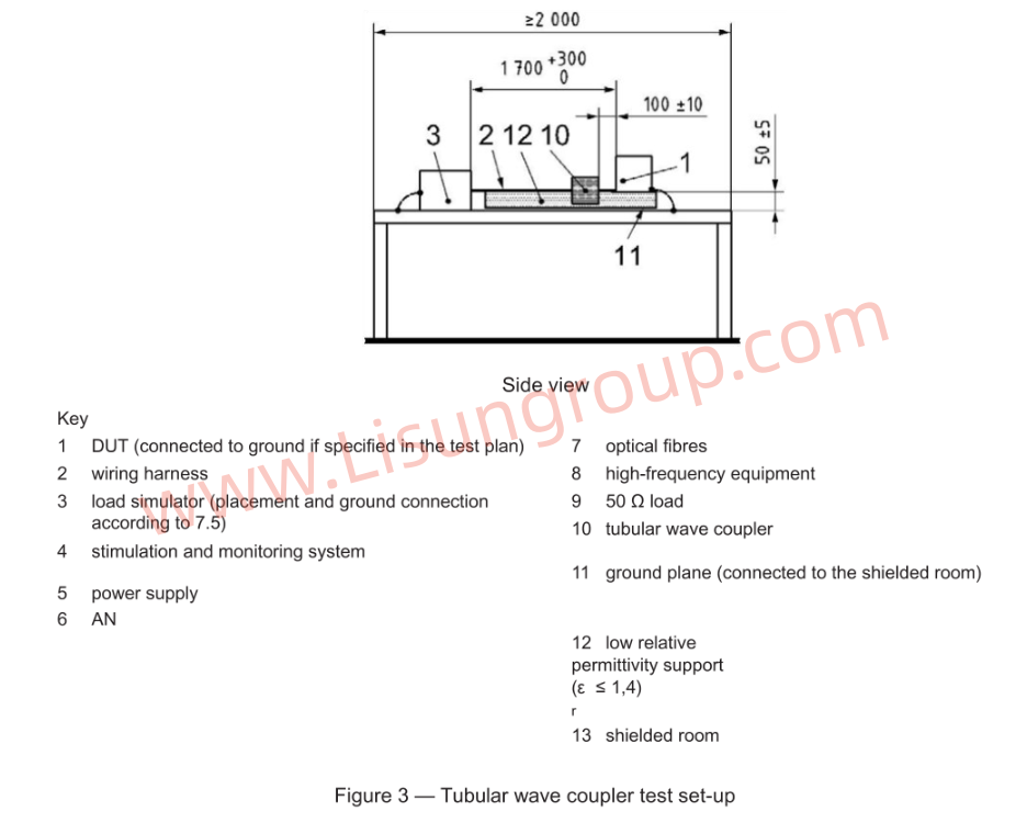
TWC Test Setup according to ISO 11452-4 Figure 3

 English
 中文简体
中文简体 English
 Русский
 Español
 Português
 Türkçe
 العربية
 Deutsch
 Polski
 Italiano
 Français
 한국어
한국어 ไทย
ไทย Tiếng Việt
 日本語
日本語






