LM-79 Moving Detector Goniophotometer (Mirror Type C)
LSG-6000

High Precision Rotation Luminaire Goniophotometer
LSG-1890B

High Precision Rotation Luminaire Goniospectroradiometer
LSG-1890BCCD

Goniophotometer for Automotive and Signal Lamps
LSG-1950

Goniophotometer for Traffic Signal Lamps
LSG-1950S

Compact Goniophotometer
LSG-1200A

Near Field Moving Detector Goniophotometer
LSG-1900B
Select an organization
to browse standards
Abstract: What is pulse magnetic field immunity? Pulse magnetic field immunity refers to the ability of electrical and electronic equipment to maintain normal functionality when subjected to transient, high-intensity pulse magnetic field interference. It is one of the key test items in the field of Electromagnetic Compatibility (EMC).
This article systematically elaborates on the physical mechanism, international standardized test methods, and engineering implementation paths for pulse magnetic field immunity. Based on the IEC 61000-4-9 standard, it analyzes the core technical indicators of pulse magnetic field generators, the design principles of induction coils, and the engineering requirements of the test system. By comparing the technical parameters of different test levels, the protection strategies against pulse magnetic field interference in industrial environments are discussed. Research indicates that the design of standardized test equipment must balance waveform fidelity, energy output stability, and operational safety, providing a technical reference for the electromagnetic compatibility design of sensitive fields such as power systems and medical equipment.
With the rapid development of modern power electronics technology, the reliability of electrical equipment in complex electromagnetic environments has become increasingly prominent. In locations such as substations, high-voltage transmission line corridors, and industrial automation sites, transient processes like switching operations, lightning strikes, and fault currents can generate pulse magnetic fields with intensities up to thousands of amperes per meter, posing serious threats to adjacent sensitive electronic equipment. As a crucial method for evaluating the electromagnetic compatibility performance of equipment, the pulse magnetic field immunity test has become a mandatory step in product certification and engineering acceptance.
The IEC 61000-4-9 standard, developed by the International Electrotechnical Commission (IEC), systematically specifies the waveform parameters, test levels, and implementation methods for the pulse magnetic field immunity test, providing a unified technical basis for EMC testing globally. Understanding what pulse magnetic field immunity is and its test principles holds significant practical value for engineering personnel in correctly selecting test equipment and designing protection schemes. This article will systematically discuss the pulse magnetic field immunity test system from three dimensions: standard specifications, core technologies, and engineering applications.
IEC 61000-4-9:2016 “Electromagnetic compatibility (EMC) – Part 4-9: Testing and measurement techniques – Pulse magnetic field immunity test” is the current international authority standard for pulse magnetic field testing. This standard is a core component of the immunity tests within the IEC 61000 series and complements IEC 61000-4-8 (Power frequency magnetic field immunity test), together covering magnetic field interference scenarios with different frequency characteristics.
The standard clearly specifies the waveform characteristics of the test magnetic field: the pulse rise time is 8 ± 20% μs, and the duration (to half-value) is 20 ± 20% μs, with the waveform being a unipolar exponentially decaying pulse. This waveform effectively simulates the typical transient magnetic field interference generated by switching operations in power systems. The standard also defines five test levels (Level 1 to Level 5), with magnetic field strengths ranging from 10 A/m to 1000 A/m, to accommodate the severity requirements of different application environments.
| Test Level | Magnetic Field Strength (A/m) | Typical Application Scenarios |
| Level 1 | 10 | Protected environments, e.g., computer rooms |
| Level 2 | 30 | General industrial environments, away from protected areas |
| Level 3 | 100 | Typical industrial environments, near distribution panels |
| Level 4 | 300 | Severe industrial environments, e.g., high-voltage substations |
| Level 5 | 1000 | Specifically severe environments, requiring custom assessment |
The selection of the test level should be based on an electromagnetic compatibility risk assessment of the equipment’s intended installation environment. For safety-critical applications such as medical equipment and nuclear power control systems, passing Level 4 or Level 5 tests is typically required to ensure functional integrity under extreme conditions.
The pulse magnetic field generator is the core equipment of the test system, and its technical implementation relies on a high-voltage pulse forming network. A typical circuit uses a capacitor charging and fast-switch discharging topology: a high-voltage DC power supply charges an energy storage capacitor to a preset voltage. A trigger signal then controls a fast switching device (such as a spark gap or solid-state switch) to discharge instantaneously, forming a large current pulse that flows through the induction coil.
Waveform control is a key technical challenge in the design. To achieve the 8/20 μs waveform specified by the standard, the circuit’s inductance, resistance, and capacitance parameters must be precisely matched. Stray inductance in the loop must be controlled to the microhenry level; otherwise, the waveform front will slow down. Concurrently, the choice of damping resistor must balance the peak current requirement with the waveform decay characteristics to avoid oscillation or overshoot. Modern generator designs employ coaxial structure layouts and low-inductance busbar technology to minimize the impact of parasitic parameters on the waveform.
The induction coil, as the magnetic field coupling element, directly determines the accuracy and repeatability of the test. The standard specifies two standard coil structures: a 1m side length square coil for testing table-top equipment, and a 1m diameter circular coil for testing floor-standing equipment. The number of coil turns is typically single or double, balancing the relationship between magnetic field strength and coil inductance.
Field uniformity is a core indicator in coil engineering design. According to the Biot-Savart law, the magnetic field distribution is most uniform in the central region of the coil, while there is significant attenuation in the edge areas. The standard requires that within the test volume occupied by the equipment (typically a 0.6m × 0.6m × 0.5m space at the coil’s center), the magnetic field strength should remain within ±3 dB of the nominal value. To achieve this goal, high-end coil designs use finite element simulation to optimize the conductor cross-sectional shape and introduce compensation windings to improve the edge field distribution.
Accurate field strength measurement is fundamental to ensuring the traceability of test results. The standard recommends using Hall effect sensors or Faraday induction coils as field probes, with a frequency response covering the DC to 1 MHz range to fully capture the pulse waveform. The calibration process must be conducted in a reflection-free shielded environment, comparing against a standard probe with metrological traceability to ensure the measurement uncertainty is better than ±1 dB.
Modern test systems integrate digital waveform acquisition functions, recording the magnetic field waveform in real-time via high-speed sampling (typically ≥10 MS/s), and automatically calculating key parameters such as peak field strength, rise time, and duration. Software algorithms need noise suppression and baseline correction capabilities to eliminate the impact of environmental electromagnetic noise on measurement accuracy.

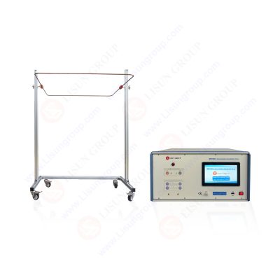
IMF61000-9 Impulse Magnetic Field Generator
Pulse magnetic field generators operate under high voltage and large current conditions, so the mechanical structure design must consider both electrical insulation and operational safety. The equipment enclosure is typically constructed from cold-rolled steel plate or aluminum alloy profiles, with a plastic-sprayed surface finish to meet an IP20 or higher protection level. High-voltage energy storage capacitor banks must be equipped with pressure relief devices and over-temperature protection to prevent the risk of rupture under fault conditions.
Ergonomic design is reflected in the control panel layout and emergency stop mechanisms. The control panel should integrate functions such as charging voltage display, trigger control, and status indication, and be equipped with a physical emergency stop button for rapid power disconnection. For generators rated at 1000 A/m, the induction coil requires a non-metallic former material (such as epoxy fiberglass laminate) to ensure mechanical strength while avoiding waveform distortion caused by eddy current losses.
The test equipment itself must possess excellent electromagnetic compatibility performance to prevent the strong pulse field from interfering with its control circuits. Key measures include: physical isolation of control and power circuits, optical fiber signal transmission, and the use of shielded cables and filters. The grounding system design follows the single-point grounding principle, separating the power ground line from the signal ground line before they are connected together, to avoid common-mode interference introduced by ground loops.
A shielded room or semi-anechoic chamber is a necessary condition for conducting high-level tests. Shielding effectiveness needs to be greater than 80 dB across the 10 kHz to 1 GHz range to isolate the external electromagnetic environment and prevent test signal leakage. The door, ventilation openings, and power filters of the shielded room are primary paths for electromagnetic leakage and require treatment with specialized shielding components such as fingerstock gaskets and waveguide cutoff vents.
In the field of pulse magnetic field immunity testing, the IMF61000-9 series pulse magnetic field generator developed by Lisun Group represents the technological level of current industrial-grade test equipment. This series of products is designed in strict accordance with IEC 61000-4-9 and GB/T 17626.9 standards, covering application needs from basic R&D to certification testing.
The IMF61000-9 features a modular energy storage unit design, with standard configuration supporting a wide range of field strength outputs from 100 A/m to 1000 A/m. Its core circuit combines a low-inductance capacitor bank (total inductance <2 μH) with a high-speed vacuum switch, ensuring the output waveform meets the strict 8/20 μs tolerance requirements under rated load. The built-in digital control system supports automatic charging voltage calculation, automatically optimizing the operating point based on the coil parameters and target field strength, significantly reducing operational complexity.
| Technical Parameter | Specification | Engineering Significance |
| Output Field Strength Range | 100–1000 A/m | Covers all standard test level requirements |
| Waveform Parameters | 8 ± 20% μs / 20 ± 20% μs | Strictly conforms to IEC 61000-4-9 waveform definition |
| Load Adaptability | Supports 1m square/circular standard coils | Compatible with testing different EUT sizes |
| Trigger Modes | Manual/Automatic/Remote control | Meets laboratory automation integration needs |
| Safety Protection | Overvoltage, Overcurrent, Overtemperature, Door Interlock | Ensures safety during high-voltage operation |
The induction coil for the IMF61000-9 is wound using oxygen-free copper strip, with an optimized cross-sectional design to reduce skin effect losses. The coil former is made of high-strength epoxy resin composite material, maintaining structural stability when subjected to pulsed electromagnetic forces. The calibration coil supplied with the equipment operates on the Rogowski coil principle, offering excellent linearity and frequency response, and can be directly traced to national electromagnetic measurement standards.
In the field of power system automation, the IMF61000-9 is widely used for type testing of protection relays, smart meters, and distribution terminals. A provincial electric power research institute used this equipment to complete a Level 4 test on a merging unit for a 500 kV substation, verifying the device’s sampling accuracy stability under 300 A/m pulse magnetic field interference.
Medical equipment manufacturers utilize this series for electromagnetic compatibility validation of MRI-compatible patient monitors. By simulating the transient magnetic field during a superconducting magnet quench in an MRI device, the functional safety performance of the monitor during strong magnetic field switching is assessed. Test results indicated that the prototype, with optimized shielding design, could withstand Level 5 (1000 A/m) tests without alarm failures or data loss.
Certification testing for railway signaling systems is another important application area. Addressing the pulse magnetic field requirements for trackside signaling equipment specified in the EN 50121-4 standard, the IMF61000-9, combined with a specialized 3D coil array, enables comprehensive exposure testing of large cabinets, ensuring equipment reliability in the complex electromagnetic environment of electrified railways.
When selecting a pulse magnetic field immunity test system, the following technical factors need comprehensive evaluation: First, confirm whether the generator’s output capability covers the field strength required for the target certification level, reserving a margin of over 20% to account for coil losses and calibration deviations. Second, examine the waveform control accuracy, especially the rise time tolerance and oscillation suppression capability, as these directly affect test repeatability. Finally, assess the supplier’s technical support capabilities, including standard update tracking, calibration services, and support for custom coil design.
High-level pulse magnetic field testing imposes special requirements on laboratory infrastructure. Besides electromagnetic shielding, consideration must be given to the disturbance strong pulse currents cause to the mains power grid; it is advisable to configure a dedicated power supply circuit or isolation transformer. The test area should be equipped with safety interlocks and warning signs to ensure operators maintain a safe distance from high-voltage charging components. For tests at the 1000 A/m level, the risk of eddy current heating in structural steel reinforcement needs assessment; constructing the test platform using non-magnetic materials may be necessary.
The current IEC 61000-4-9 standard primarily focuses on unipolar pulse magnetic fields, whereas actual power system faults can generate oscillatory or bipolar magnetic fields. Future standard revisions may expand the waveform types, requiring test equipment to have waveform programmability to adapt to new requirements. Furthermore, with the proliferation of wide-bandgap semiconductor devices, increased switching speeds lead to significantly higher magnetic field change rates (dB/dt), posing greater challenges to the bandwidth of test systems and the response speed of sensors.
This article systematically elaborated on what is pulse magnetic field immunity and its core position in electromagnetic compatibility engineering. Based on the IEC 61000-4-9 standard framework, it analyzed the key technical elements of pulse magnetic field generators, including waveform forming circuits, induction coil optimization, and calibration methods. Research indicates that the design of standardized test equipment must strike a balance between electrical performance, mechanical structure, and operational safety to meet the stringent requirements of industrial applications.
On the engineering practice level, the IMF61000-9 series equipment, through modular energy storage design, precise waveform control, and comprehensive safety mechanisms, provides reliable test solutions for fields such as power, medical, and rail transportation. With the development of smart grid and Industry 4.0 technologies, pulse magnetic field immunity testing will play an increasingly important role in ensuring the electromagnetic safety of critical infrastructure. It is recommended that engineers in related fields deeply understand the standard’s essence, rationally allocate test resources based on specific application needs, and build a robust electromagnetic compatibility assurance system.
Tags:IMF61000-9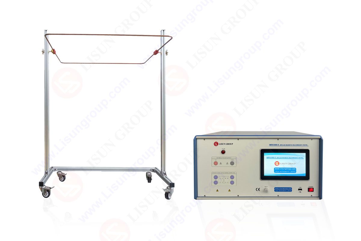

 中文简体
中文简体