LM-79 Moving Detector Goniophotometer (Mirror Type C)
LSG-6000

High Precision Rotation Luminaire Goniophotometer
LSG-1890B

High Precision Rotation Luminaire Goniospectroradiometer
LSG-1890BCCD

Goniophotometer for Automotive and Signal Lamps
LSG-1950

Goniophotometer for Traffic Signal Lamps
LSG-1950S

Compact Goniophotometer
LSG-1200A

Near Field Moving Detector Goniophotometer
LSG-1900B
Select an organization
to browse standards
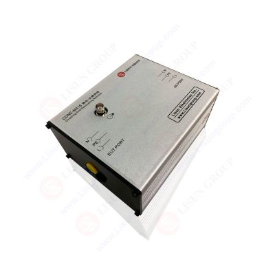
Coupling/Decoupling Networks (CDNEs) play a fundamental role in electromagnetic compatibility (EMC) testing, providing critical interface between Electromagnetic Interference (EMI) receivers and Equipment Under Test (EUT). This comprehensive technical analysis examines working principles, technical specifications, and practical applications of CDNEs in modern EMC test systems. CDNE-M316 represents a specialized implementation designed for measuring radio disturbance characteristics of electrical lighting and similar equipment across the 30-300MHz frequency range. The question of what is CDNE in EMC testing is addressed through detailed exploration of coupling and decoupling mechanisms, frequency response characteristics, and standards compliance requirements that influence accurate EMC testing.
Technical specifications demonstrate CDNE-M316 capabilities and application scope, with emphasis on 30-300MHz frequency range optimized for lighting equipment disturbances. This research provides detailed insights for engineers and EMC professionals on CDNE technology, facilitating informed selection and proper utilization of coupling/decoupling networks for reliable electromagnetic disturbance measurements and regulatory compliance verification. The analysis includes comparative performance data across different application domains and practical implementation considerations for laboratory environments.
Coupling/Decoupling Networks (CDNEs) represent essential test equipment in electromagnetic compatibility testing, specifically designed to measure conducted radio disturbances generated by electrical and electronic equipment. Understanding what is CDNE in EMC testing requires examining fundamental requirement of providing a controlled interface between test equipment and devices under test. CDNE technology enables accurate measurement of electromagnetic interference characteristics while maintaining proper isolation from auxiliary power supplies and measurement instruments.
The core function of a CDNE encompasses two primary mechanisms: coupling transfers disturbance signals from Equipment Under Test (EUT) to measurement receivers with appropriate signal characteristics, while decoupling isolates measurement system from power circuits and auxiliary connections that could introduce measurement errors. CDNEs must maintain specific impedance characteristics as required by measurement standards to ensure measured signals accurately represent radio disturbance characteristics of test samples.
In context of EMC testing, CDNEs facilitate standardized measurements of conducted disturbances, particularly in frequency range from 9kHz to 30MHz and extending to higher frequencies as required by specific applications. Modern CDNE implementations, such as CDNE-M316, operate across the 30-300MHz frequency range, addressing the high-frequency spectrum of conducted disturbances generated by contemporary lighting equipment. This extended frequency coverage addresses electromagnetic interference (EMI) characteristics of modern lighting technologies, including LED systems with switching power supplies that generate significant electromagnetic activity requiring proper measurement for regulatory compliance.
The development of CDNE technology has evolved significantly alongside the advancement of electronic systems and the increasing complexity of electromagnetic compatibility requirements. Early EMC testing primarily focused on radiated emission measurements, but recognition of conducted disturbances as a critical issue led to establishment of specific requirements for coupling/decoupling networks. The evolution of EMC standards, particularly CISPR 15 for lighting equipment, has driven substantial improvements in CDNE design and performance specifications.
Modern CDNE implementations, such as the CDNE-M316, incorporate sophisticated circuit topologies to address demanding requirements while supporting automated test configurations and enhanced measurement accuracy. These networks must maintain precise impedance characteristics across broad frequency ranges while providing adequate signal coupling and effective decoupling from auxiliary power supplies. The CDNE-M316 demonstrates current industry practice through its specialized design for lighting equipment applications, including the 30-300MHz frequency coverage that indicates optimization for the spectral characteristics of lighting device disturbances.
The coupling function in CDNEs implements precise signal transfer mechanisms that enable measurement receivers to detect conducted disturbances from equipment under test. The CDNE-M316 and similar devices employ capacitor-based coupling circuits that inject disturbance signals from signal lines or power conductors of the EUT into measurement receivers. These coupling mechanisms must maintain controlled impedance characteristics throughout the operating frequency range, typically requiring common-mode impedance of 150Ω with specified tolerances as prescribed by EMC standards.
Effective coupling design considers the frequency-dependent behavior of coupling elements, ensuring consistent performance across the 30-300MHz range of the CDNE-M316. Signal integrity considerations are paramount, as CDNEs must introduce minimal distortion while preserving the waveform characteristics of injected disturbance signals. Advanced implementations incorporate high-quality capacitors with low loss characteristics and precision resistors to achieve these performance goals across broad frequency ranges. The coupling network must handle various signal types, including AC power, DC power, and signal interfaces, through multi-channel designs that support diverse testing scenarios.
The decoupling function implements isolation mechanisms that prevent test signals from affecting auxiliary equipment, power supplies, or measurement instruments. CDNE-M316 employs multi-stage decoupling including common-mode chokes and line filters to achieve isolation requirements while maintaining adequate power delivery capability for equipment under test. These decoupling mechanisms must present high impedance to disturbance signals at power interfaces, effectively preventing test signal contamination of auxiliary connections.
Decoupling effectiveness varies with frequency, load conditions, and specific configurations of auxiliary connections. The decoupling network must handle the full operational current of equipment under test without saturation or excessive voltage drop, requiring careful magnetic component design and appropriate core material selection. Asymmetric decoupling may occur in multi-phase systems, necessitating balanced circuit topology to ensure consistent performance across all phases. The interaction between coupling and decoupling functions represents a critical design consideration, as optimization of one function must not compromise performance of the other in the context of comprehensive CDNE EMC testing protocols.
CDNE system frequency response determines their applicability across different test scenarios and standards. Modern CDNE implementations including CDNE-M316 are designed to cover frequency ranges from 9kHz to 30MHz or higher, addressing most conducted disturbance phenomena associated with current electronic equipment. Within these ranges, coupling factors must be maintained within specified tolerances, typically exhibiting deviations of less than ±1.5dB from nominal values. Decoupling performance exhibits frequency-dependent characteristics, with higher decoupling ratios typically achieved at lower frequencies due to the enhanced effectiveness of inductive isolation mechanisms.
Phase response characteristics also influence testing accuracy, particularly for immunity testing where timing relationships between multiple disturbance signals may be critical. High-quality CDNE designs maintain linear phase characteristics across their operational bandwidth, minimizing signal distortion and ensuring that disturbance waveforms reaching the EUT accurately represent intended test signals. Transition characteristics between frequency ranges must be carefully managed to avoid abrupt changes in coupling or decoupling performance that could introduce measurement uncertainty or repeatability issues in CDNE EMC testing applications.
Impedance characteristics represent fundamental requirements for CDNE performance in EMC testing applications. Most standards specify common-mode impedance of 150Ω with tolerance requirements typically within ±20% across applicable frequency ranges. CDNE-M316 maintains these impedance characteristics through careful component selection and circuit topology optimization. The impedance matching between CDNE, test equipment, and equipment under test influences measurement accuracy, particularly at higher frequencies where transmission line effects become significant.
Load impedance variations presented by different equipment under test must be accommodated without significant performance degradation. Modern CDNE designs incorporate impedance stabilization networks that maintain consistent impedance characteristics across varying load conditions. The impedance characteristics must remain stable over environmental conditions including temperature variations that could affect component values and circuit performance. Temperature compensation techniques may be employed in advanced CDNE implementations to maintain consistent impedance characteristics across operating temperature ranges typically spanning laboratory environments from 0°C to 50°C.
Table 1: Technical Specifications of CDNE-M316 Coupling/Decoupling Network
| Parameter | Specification | Tolerance | Standard Reference | Application |
| Frequency Range | 30-300 MHz | ±5% | CISPR 15:2018 | Lighting Equipment |
| Common Mode Impedance | 150 Ω | ±20% | CISPR 15:2018 | All Frequencies |
| Coupling Attenuation | 0 dB | ±1.5 dB | CISPR 15:2018 | Signal Transfer |
| Decoupling Attenuation | >40 dB | Minimum | CISPR 15:2018 | 30 MHz – 300 MHz |
| Standards Compliance | CISPR 15:2018 | Full Compliance | International | Lighting Standards |
| Regional Standards | EN55015, GB17743-2007 | Full Compliance | Regional | EU & China Markets |
Table 1 presents technical specifications of CDNE-M316 coupling/decoupling network, demonstrating comprehensive performance capabilities across key parameters. The 30-300MHz frequency range addresses high-frequency conducted disturbances typical of modern lighting equipment. Full compliance with international standards including CISPR 15:2018, EN55015, and GB17743-2007 ensures global applicability for EMC testing requirements. Technical parameters are optimized for lighting equipment testing applications while maintaining versatility for broader conducted disturbance measurement needs.
CISPR 15:2018 establishes comprehensive requirements for electromagnetic compatibility testing of electrical lighting and similar equipment. This standard specifies measurement methods and limits for radio disturbance characteristics, requiring the use of coupling/decoupling networks to ensure accurate measurement of conducted disturbances across frequency ranges typically spanning 9kHz to 30MHz with extensions to higher frequencies for certain applications. CDNE-M316 is specifically designed to address the 30-300MHz frequency range, covering the high-frequency spectrum of conducted disturbances generated by modern lighting equipment.
The standard establishes detailed test requirements including specific configurations for coupling/decoupling networks, measurement receiver characteristics, and test procedures for various types of lighting equipment. CISPR 15:2018 compliance is mandatory for many lighting products in multiple jurisdictions, making accurate CDNE-based testing essential for market access and regulatory approval. CDNE-M316 meets the requirements of the standard through its design specifications, providing lighting manufacturers with testing capabilities that satisfy international measurement methodology requirements. Global acceptance of the standard ensures that testing using CDNE-M316 produces comparable results across different countries and regions.
In addition to CISPR 15:2018, CDNE-M316 demonstrates compliance with regional standards that implement or reference international standards within specific geographic regulatory frameworks. EN55015 represents the European equivalent standard for electromagnetic compatibility requirements of lighting equipment, specifying equivalent or identical measurement methods and disturbance limits. Compliance with EN55015 is essential for lighting products sold in the European Economic Area, requiring CDNE-based testing that meets European specifications. CDNE-M316 satisfies EN55015 requirements through its design and calibration.
GB17743-2007 represents the Chinese national standard for measuring radio disturbance characteristics of electrical lighting and similar equipment. CDNE-M316 compliance with GB17743-2007 ensures that lighting products tested with this equipment meet Chinese electromagnetic compatibility regulatory requirements. The coexistence of these regional standards demonstrates the global influence of the international framework and its importance in EMC requirements for the lighting industry. Manufacturers seeking market access across different regions must ensure that their CDNE-based testing addresses applicable regional standards, potentially requiring multiple certification activities.
CDNE technology finds primary application in measuring radio disturbance characteristics of electrical lighting and similar equipment. This application directly addresses the scope of CISPR 15:2018, EN55015, and GB17743-2007 standards which focus on electromagnetic compatibility of lighting products. Lighting equipment including LED lamps, fluorescent fixtures, ballasts, lighting control systems, and similar products must demonstrate compliance with radio disturbance limits to ensure they do not interfere with radio broadcasting, wireless communications, and other radio services. CDNE-M316 works with EMI receivers to provide the specialized interface required for accurate measurement of conducted radio disturbances.
Testing lighting equipment using CDNE-M316 involves connecting the test product to the CDNE interface according to standard procedures, with the CDNE then connected to EMI receivers for measurement. Measured disturbance levels are compared to limits specified in applicable standards to determine compliance status. This testing is critical for product certification, market access compliance, and quality control in lighting manufacturing. CDNE-M316 design for lighting applications, including the 30-300MHz frequency range, indicates optimization for the spectral characteristics of lighting equipment disturbances, potentially offering enhanced accuracy compared to general-purpose CDNE implementations.
Effective implementation of CDNE-M316 in EMC test systems requires proper integration with EMI receivers and consideration of overall measurement system performance. The specification that CDNE-M316 works with EMI receivers indicates intended use in coordinated measurement systems where the CDNE provides coupling and decoupling functions while the EMI receiver performs signal measurement and analysis. System integration considerations include ensuring compatibility between CDNE and receiver interfaces, appropriate cabling practices that maintain signal integrity, and proper grounding and shielding for the complete test setup.
Integration best practices include minimizing cable lengths between CDNE-M316 and EMI receivers to reduce parasitic effects that could affect high-frequency measurement accuracy. Proper shielding of the complete measurement chain, including CDNE, cables, and receiver enclosure, prevents external electromagnetic interference from affecting measurements. Test setup must implement grounding arrangements specified by applicable standards, which typically include specific connections to reference ground, protective earth, or other ground points to ensure consistent and accurate measurements. System calibration covering the entire measurement chain provides verification that the complete system meets compliance testing accuracy requirements.
Regular calibration of CDNE equipment ensures that measurement accuracy is maintained over time, with typical calibration intervals specified by manufacturers or determined by usage intensity and required measurement uncertainty in laboratory quality procedures. The CDNE-M316 calibration process involves measuring performance parameters against reference standards traceable to national measurement laboratories. The resulting calibration certificates document actual measured values compared to specified requirements, providing users with measurement accuracy confidence and supporting compliance verification processes.
Appropriate calibration maintenance ensures that CDNE-based testing continues to produce reliable, defensible results throughout the service life of the equipment. Calibration considerations include verification of frequency response, coupling factor accuracy, impedance parameters, and decoupling effectiveness. Traceability to national measurement laboratories ensures that calibration results can be related to international measurement standards, supporting the international recognition of test results. Documentation of calibration activities must be maintained to support quality management system requirements and to provide traceability of measurement accuracy over the equipment’s operational lifetime.
Selecting CDNE equipment for EMC testing applications requires engineers to carefully evaluate multiple factors to ensure optimal performance and cost-effectiveness. Primary considerations involve matching CDNE specifications to requirements of applicable standards and characteristics of equipment under test. Current handling capacity must exceed the maximum operational current of the EUT with adequate margin to accommodate inrush currents and temporary overload conditions. Frequency coverage should encompass the full range specified by relevant standards, with consideration for future needs as standards evolve to address higher frequency phenomena.
Coupling factor options and adjustment capability should support test levels required by target standards without introducing external attenuators that may add measurement uncertainty. Interface connector configurations must accommodate wiring requirements of equipment under test and provide appropriate adapters for non-standard connections. Brand reputation and technical support capabilities deserve consideration, as reliable access to calibration services, technical documentation, and application expertise can significantly influence long-term equipment utility and total cost of ownership. Price-performance analysis should balance initial procurement cost against long-term reliability, calibration stability, and upgrade potential.
Measurement uncertainty represents a critical consideration in CDNE-based EMC testing, particularly for applications where test results approach specified limits. Sources of measurement uncertainty in CDNE systems include component tolerances, calibration uncertainties, environmental variations, and systematic errors in test setup. CDNE-M316 design includes features that minimize measurement uncertainty through precision component selection, temperature compensation, and optimized circuit topology. Understanding and quantifying measurement uncertainty enables laboratories to establish appropriate safety margins when interpreting test results relative to standard limits.
Measurement uncertainty analysis considers contributions from all elements of the measurement chain including CDNE characteristics, cable effects, receiver accuracy, and environmental conditions. High-quality CDNE implementations maintain consistent performance across environmental variations including temperature, humidity, and electromagnetic conditions. Documentation of measurement uncertainty budgets and calibration traceability supports regulatory acceptance of test results and facilitates international recognition of certification activities. Advanced CDNE systems may incorporate uncertainty estimation features that provide real-time assessment of measurement accuracy during test execution.
The evolution of CDNE technology continues to advance to address emerging challenges in electromagnetic compatibility testing. Higher frequency capabilities are becoming increasingly important as new wireless communication technologies and high-speed digital interfaces generate conducted disturbances at frequencies exceeding 30MHz. Advanced CDNE implementations are incorporating frequency coverage extending to 300MHz and beyond to address these emerging requirements. Integrated measurement capabilities represent another trend, with next-generation CDNEs incorporating built-in monitoring functions that provide real-time verification of coupling levels, decoupling effectiveness, and other critical parameters during test execution.
Digital control and calibration features support automated verification procedures, reducing requirements for external measurement equipment and simplifying quality assurance processes. Trends toward software-defined test instrumentation are influencing CDNE design, with programmable coupling networks that can adapt to different standards and test scenarios through firmware updates without hardware modifications. Enhanced connectivity including Ethernet, USB, and wireless interfaces facilitates integration with modern automated test systems and remote monitoring capabilities. These developments collectively enhance the versatility, accuracy, and efficiency of CDNE EMC testing for evolving electronic system requirements.
Table 2: Performance Comparison Across Application Domains
| Application | Current Rating | Frequency Range | Channels | Coupling Options | Key Requirements |
| Lighting Equipment | 10-16 A | 30-300 MHz | 2-4 | Fixed | CISPR 15 Compliance |
| Consumer Electronics | 10-16 A | 9 kHz – 30 MHz | 2-4 | Variable | IEC 61000-4-6 |
| Automotive | 20-32 A | 150 kHz – 80 MHz | 4-8 | Variable | ISO 11452-4 |
| Medical | 16 A | 9 kHz – 30 MHz | 2-4 | Precision | IEC 60601-1-2 |
| Industrial | 32-64 A | 9 kHz – 30 MHz | 4-12 | Variable | IEC 61000-4-6 |
Table 2 provides comparative performance analysis of CDNE implementations across different application domains. Lighting equipment applications require the 30-300MHz frequency range characteristic of CDNE-M316, addressing the specific spectral characteristics of modern lighting technologies. Consumer electronics applications typically focus on the 9kHz-30MHz range specified by IEC 61000-4-6. Automotive applications demand higher current ratings and extended frequency coverage to address complex electromagnetic environments. Medical equipment requires precision coupling characteristics to meet stringent IEC 60601-1-2 requirements. Industrial applications require robust current handling capabilities for high-power equipment testing.
Coupling/Decoupling Networks represent fundamental components in modern EMC test infrastructure, enabling precise evaluation of electromagnetic disturbance characteristics across diverse electronic products. This comprehensive analysis has elucidated the working principles, technical specifications, and engineering considerations for CDNE implementation in EMC test laboratories. The question of what is CDNE in EMC testing has been answered through detailed examination of coupling and decoupling mechanisms, frequency response characteristics, and standards compliance requirements that influence testing accuracy and regulatory compliance.
Understanding CDNE technology enables engineers to optimize testing accuracy, improve measurement repeatability, and enhance efficiency of electromagnetic compliance programs. As electronic systems continue to evolve in complexity and operational frequencies, CDNE technology must advance to address emerging challenges in electromagnetic compatibility verification. Future developments will likely expand frequency coverage, enhance integration with automated test systems, and incorporate intelligent features that improve calibration accuracy and operational convenience. Fundamental principles established by current standards provide a solid foundation for these advancements while ensuring continued harmonization of CDNE EMC testing practices across international markets and industry sectors.
Tags:CDNE-M316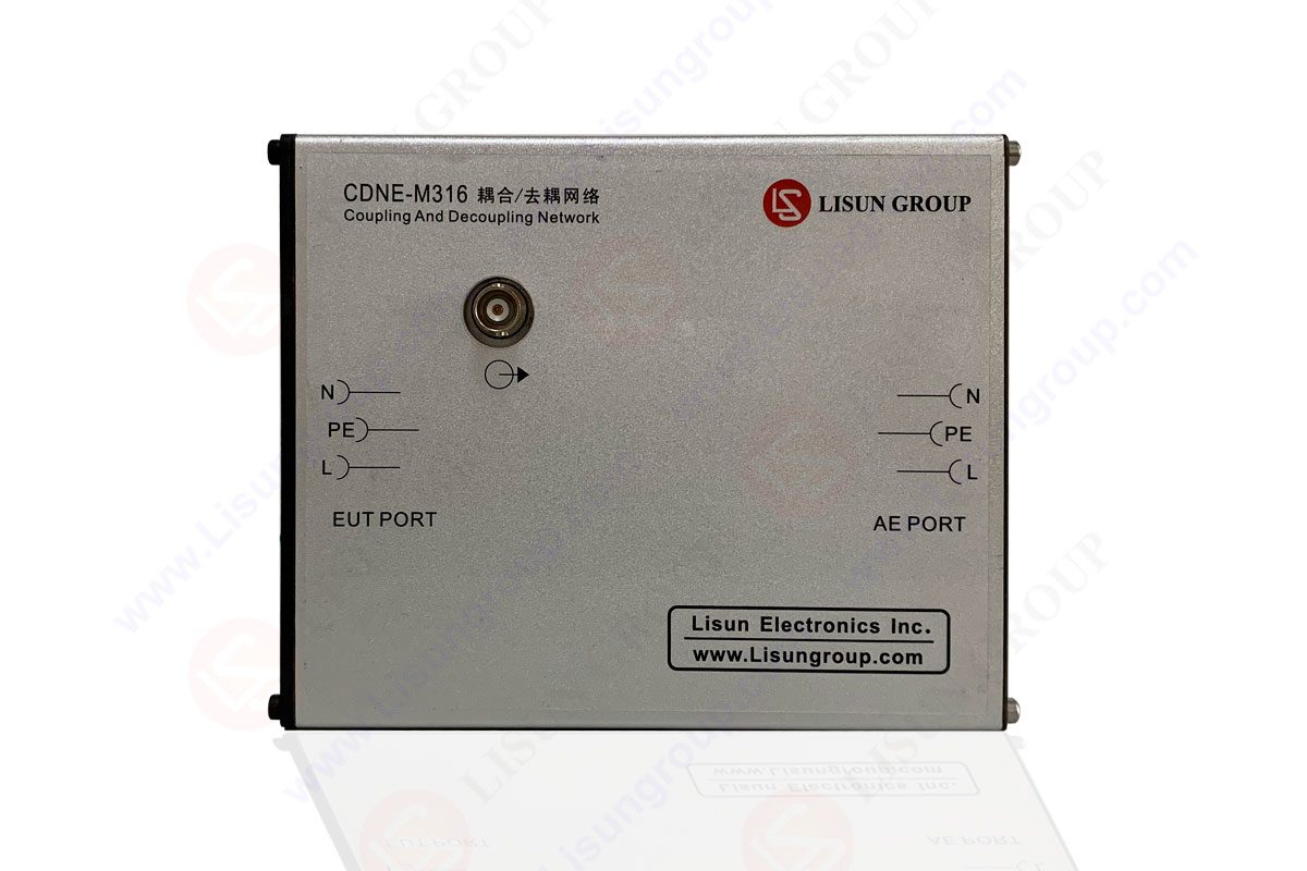

 中文简体
中文简体