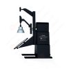
LM-79 Moving Detector Goniophotometer (Mirror Type C)
LSG-6000
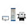
High Precision Rotation Luminaire Goniophotometer
LSG-1890B
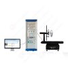
High Precision Rotation Luminaire Goniospectroradiometer
LSG-1890BCCD

Goniophotometer for Automotive and Signal Lamps
LSG-1950
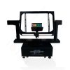
Goniophotometer for Traffic Signal Lamps (Economical Model)
LSG-1950S
VAD Fire Alarm Visual Alert Device Goniophotometer
LSG-1930
Goniophotometer for Airfield Lighting
LSG-1940
Compact Goniophotometer
LSG-1200A
LED Goniophotometer
LSG-1100
Near Field Moving Detector Goniophotometer
LSG-1900B
 LEDs and Luminaire Test Solutions
 LM-79 and LM-80 Test Solutions
 LED Driver Test Solutions
 Household Appliances Test Solutions
 Mobile and Network Test Solutions
 Automotive Electronics Test Solutions
 Audio-Video and IT Test Solutions
 Cable and Wire Test Solutions
 Plugs and Sockets Test Solutions
 Power Switch Test Solutions
 Transformer Test Solutions
 Electric Toys Test Solutions
 Energy Meter Test Solutions
 Motor-Operated Tool Test Solutions
Select an organization
to browse standards
Abstract
High‑amplitude, short‑duration voltage spike transient interferences will be generated during load switching and relay on‑off of aircraft power busbars. These interferences couple into airborne electronic equipment through AC/DC power input ports and may result in component damage, program abnormality and communication interruption. As a critical EMC test item for airworthiness verification of civil aviation airborne equipment, RTCA DO‑160 Section 17 requires dedicated Voltage Spike Generator to reproduce real‑world spike pulses from airborne power grid and complete voltage spike susceptibility immunity test for equipment. Taking LISUN DO160‑S17 Voltage Spike Pulse Generator as the research object, this paper illustrates equipment principle, test preparation, complete test procedure and result judgment criteria of Voltage Spike Generator. It provides practical references for voltage spike immunity test on power ports of civil aviation airborne equipment and military avionics following RTCA DO‑160 Section 17 specification.
A large number of inductive loads are equipped in aircraft airborne power supply system. When airborne busbar executes load switching and electromagnetic relay make‑and‑break operations, rapid energy release from inductor magnetic field generates voltage spike transients with short rise time and pulse width of about 10μs. These interferences directly act on power input ports of airborne electronic equipment. In mild cases, they cause drift of equipment operating parameters and communication bit errors; in severe cases, power chips and protective devices may be broken down, leading to permanent damage of airborne equipment and directly threatening the operational safety of aviation platforms.
The RTCA DO‑160 Section 17 voltage spike test is designed to verify whether the equipment under test (EUT) can maintain full functionality or avoid permanent hardware damage when subjected to transient spike impacts on power lines. The test covers AC and DC powered airborne equipment, applicable to civil aviation, helicopters and some military avionics equipment adopting this standard. The standard classifies EUT into Category A and Category B. Category A equipment shall withstand maximum 600 V open‑circuit spike voltage for airborne equipment with high spike protection requirements. For Category B equipment, test voltage shall be the smaller value between twice rated working voltage of equipment and 200 V with relatively lower protection requirement. The whole test shall be implemented by Voltage Spike Generator complying with standard waveform specifications. Ordinary surge and lightning test equipment cannot substitute for this test.
LISUN DO160‑S17 Voltage Spike Pulse Generator is a dedicated Voltage Spike Generator developed for RTCA DO‑160 Section 17 voltage spike susceptibility test. Waveform output parameters fully meet constraints of aviation standard. The unit is equipped with Android intelligent control system and supports WIFI connection with tablet for remote operation. Output polarity can be switched among positive, negative and alternating positive‑negative modes. Stable continuous pulse output is available for long‑time operation to satisfy test demands of certification laboratories, research institutes and aviation manufacturers. This product series includes three models for different output current levels. Pulse coupling injection is realized by built‑in or external 10μs coupling transformer. Core technical parameters are shown in Table 1.
| Parameter Item | DO160‑S17 | DO160‑S17‑50A | DO160‑S17‑100A |
|---|---|---|---|
| Coupling Mode | Built‑in coupling‑decoupling network, max. 440V/16A | External 10μs coupling transformer, max. 440V/50A | External 10μs coupling transformer, max. 440V/100A |
| Test Output Voltage | 5V~1000V continuously adjustable | 5V~1000V continuously adjustable | 5V~1000V continuously adjustable |
| Pulse Rise Time | ≤2μs | ≤2μs | ≤2μs |
| Pulse Width | >10μs | >10μs | >10μs |
| Source Output Impedance | 50Ω±10% | 50Ω±10% | 50Ω±10% |
| Output Polarity | Positive, Negative, Alternating Positive‑Negative | Positive, Negative, Alternating Positive‑Negative | Positive, Negative, Alternating Positive‑Negative |
| Max. Pulse Repetition Rate | 2Hz | 2Hz | 2Hz |
| Control Mode | WIFI tablet Android software remote control | WIFI tablet Android software remote control | WIFI tablet Android software remote control |
| Equipment Operating Power Supply | 220~240V, 50/60Hz | 220~240V, 50/60Hz | 220~240V, 50/60Hz |
According to waveform definition of the standard, source impedance of Voltage Spike Generator must be kept at 50Ω, rise time no more than 2μs and pulse width greater than 10μs. These specifications directly determine transient energy injected into EUT port and become core concerns for Voltage Spike Generator selection. The DO160‑S17 series can superimpose spike pulses directly for low‑power airborne equipment via built‑in coupling‑decoupling network. For high‑current EUT, models with external coupling transformer shall be adopted to guarantee main loop power supply capacity.
Before formal RTCA DO‑160 Section 17 test, laboratory environment layout and test system setup shall be finished. The test system consists of Voltage Spike Generator, airborne simulated power supply, oscilloscope, airborne EUT and monitoring terminal. First of all, confirm that the Voltage Spike Generator has passed metrological calibration with valid waveform indicators. Prepare test classification documents of EUT and determine test voltage level for Category A or Category B.
Step one: waveform pre‑verification. Disconnect EUT, connect output terminal of Voltage Spike Generator to 50Ω standard matched load. Use oscilloscope to collect output waveforms under open‑circuit and matched‑load conditions, verify pulse rise time, pulse width, output impedance and output voltage amplitude. Confirm output waveforms comply with waveform definition of RTCA DO‑160 Section 17 and record generator setting parameters. These parameters shall be reused in subsequent tests without adjusting generator output settings due to load effect from EUT.
Step two: EUT installation and baseline confirmation. Place airborne EUT according to real installation status. EUT is connected to airborne simulated power supply through coupling network of Voltage Spike Generator and set to rated AC or DC operating voltage. Enable all equipment functions, use external monitoring terminal to collect all performance indicators such as communication, display and output, record baseline status and confirm no failure of EUT. According to standard requirements, a 10μF capacitor shall be paralleled at power input port to mitigate voltage drop of main power supply caused by spike pulses.
Step three: pulse injection test. Set output amplitude of Voltage Spike Generator according to equipment category, select positive polarity, negative polarity or alternating positive‑negative mode. Pulse repetition rate shall not exceed maximum allowable 2Hz specified by standard, and apply standard voltage spike pulses to AC/DC power input port of EUT respectively. During test, continuously monitor operating status of EUT and observe whether crash, reboot, communication error and function failure occur. Synchronously capture actual spike waveforms at power port by oscilloscope. Apply sufficient number of pulses for each polarity to complete test under all polarity conditions.
Step four: post‑test re‑verification. After completion of all spike pulse injection, keep EUT powered on, read all performance indicators again and compare with pre‑test baseline records to check performance degradation. Then power‑cycle EUT and inspect whether permanent hardware damage occurs.
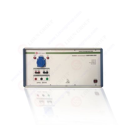
DO160-S17_Voltage Spike Generator
Referring to judgment rules of RTCA DO‑160 Section 17, there are two test result scenarios. Firstly, for Category A critical airborne equipment, EUT shall maintain all specified functions during and after voltage spike pulse injection. Abnormal operation is prohibited and no permanent hardware damage shall occur after power‑cycle reboot. Secondly, for some non‑critical Category B equipment, transient disturbance is permitted the moment spike impulse arrives, yet equipment shall automatically restore full functions after pulse termination without permanent hardware damage. If unrecoverable failure occurs, EUT is regarded as non‑compliant with this section. Modification on power port protection circuit such as adding transient suppressor devices and input filter network is required, then re‑test shall be carried out with Voltage Spike Generator.
When performing DO‑160 Section 17 test with Voltage Spike Generator, do not arbitrarily modify generator settings to compensate waveform distortion caused by EUT. Waveform deformation resulting from input impedance of EUT belongs to real test condition, and generator shall keep parameters from pre‑verification phase unchanged. Meanwhile, coupling network selection shall match operating current of EUT. Low‑power airborne equipment can adopt DO160‑S17 with built‑in CDN. High‑power avionics shall select models equipped with external coupling transformer to avoid test result deviation or equipment damage caused by current overload. WIFI remote control allows operators to stay away from high‑voltage pulse output terminal and improves operation safety for long‑duration continuous test.
RTCA DO‑160 Section 17 voltage spike test is a key item for airworthiness certification of airborne avionics. As the core instrument of the whole test system, Voltage Spike Generator’s waveform accuracy and coupling capability directly affect validity of test results. LISUN DO160‑S17 Voltage Spike Pulse Generator fully reproduces spike transients defined by aviation standard. It can be applied for voltage spike immunity test on AC/DC power ports of civil aviation airborne equipment and military avionics adopting this standard. It simulates transient spike interferences generated by aircraft busbar load switching and relay actions, verifies capability of airborne equipment against power‑line transient shocks in laboratory environment in advance and exposes hardware design defects, which delivers significant engineering value for improving reliability of aviation electronic equipment.
Tags:DO160-S17Your email address will not be published. Required fields are marked *

 English
 中文简体
 English
 Русский
 Español
 Português
 Türkçe
 العربية
 Deutsch
 Polski
 Italiano
 Français
 한국어
 ไทย
 Tiếng Việt
 日本語