
LM-79 Moving Detector Goniophotometer (Mirror Type C)
LSG-6000

High Precision Rotation Luminaire Goniophotometer
LSG-1890B

High Precision Rotation Luminaire Goniospectroradiometer
LSG-1890BCCD

Goniophotometer for Automotive and Signal Lamps
LSG-1950

Goniophotometer for Traffic Signal Lamps
LSG-1950S

VAD Fire Alarm Visual Alert Device Goniophotometer
LSG-1930

Compact Goniophotometer
LSG-1200A

LED Goniophotometer
LSG-1100
 LEDs and Luminaire Test Solutions
 LM-79 and LM-80 Test Solutions
 LED Driver Test Solutions
 Household Appliances Test Solutions
 Mobile and Network Test Solutions
 Automotive Electronics Test Solutions
 Audio-Video and IT Test Solutions
 Cable and Wire Test Solutions
 Plugs and Sockets Test Solutions
 Power Switch Test Solutions
 Transformer Test Solutions
 Electric Toys Test Solutions
 Energy Meter Test Solutions
 Motor-Operated Tool Test Solutions
Select an organization
to browse standards
Product No: GNGPL-31210
GNGPL-31210 AS/NZS 3112:2025 Clause 2.13.8 Figure 2.10 Plug Temperature Rise Clamping Unitis manufactured in full compliance with AS/NZS 3112:2025 Clause 2.13.8 and Figure 2.10, specially designed for plug temperature rise test.
The temperature rise test evaluates thermal performance of rewireable and non-rewireable Australian standard plugs under specified load conditions. Figure 2.10 defines three types of pin clamping units: (a) 10 A & 15 A flat pin type, (b) 10 A round pin type and (c) 20 A flat pin type. Each clamping unit provides standardized connection for plug live pins, reserves installation position for thermocouple and wiring space for test cables. All clamping components are brass with minimum 52% copper content as specified in the standard. During testing, 1.1 times rated current shall be applied continuously for 1 hour, and the temperature rise measured by thermocouple cannot exceed 45 K.
Specifications:
• Applicable Standard: AS/NZS 3112:2025 Clause 2.13.8, Figure 2.10
• Included Clamping Units:
Figure 2.10(a): For 10 A & 15 A flat pin plugs
Figure 2.10(b): For 10 A round pin plugs
Figure 2.10(c): For 20 A flat pin plugs
• Material: Brass with copper content ≥ 52%
• Clamping Screw: M3.50, maximum length 12 mm
• Specified tightening torque for clamping screw: 0.8 Nm
• Test current requirement: 1.1 × rated current of plug, energized for 1 hour
• Pass criterion: Temperature rise ≤ 45 K
• Test environment: Draught-free space; plug fixed on 6±2 mm wooden board (500 mm × 500 mm) inside 90×60×40 mm wooden wall box
Test Procedures:
• Mount the corresponding Figure 2.10 clamping unit onto each live pin of the test plug.
• Install the thermocouple in the reserved fixed area on the clamping unit, fasten the clamping screw with a torque of 0.8 Nm.
• Connect at least 1 m long PVC insulated conductors with nominal cross-sectional area to the clamping unit.
• Ensure airtight sealing where conductors pass through the wooden mounting enclosure.
• Feed alternating current equal to 1.1 times the plug rated current through each live pin and clamping unit for continuous 1 hour.
• For plugs with three or more poles, complete test on phase contacts firstly; carry out separate tests on neutral contact and adjacent phase contact if available.
• Record temperature data from thermocouple and judge whether temperature rise is within the limit of 45 K.
• Non-rewireable plugs are tested with minimum specified conductor cross-section.
• Rewireable plugs shall be assembled with minimum cross-section cords and terminal screws tightened to two-thirds torque value defined in Table 2.2 Test No.5.
Applications:
• Temperature rise test for AS/NZS 3112 standard plugs according to Clause 2.13.8
• Pre-compliance testing before SAA safety certification
• Thermal performance verification during plug product R&D and mould optimization
• Quality periodic inspection for plug manufacturers
• Standard test fixture for third-party electrical safety laboratories
• Performance comparison test between rewireable and non-rewireable Australian plugs
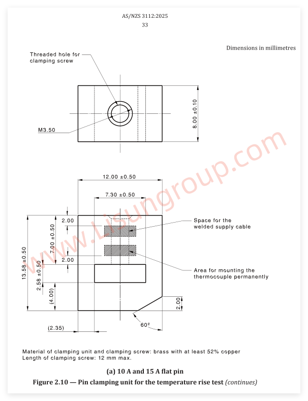
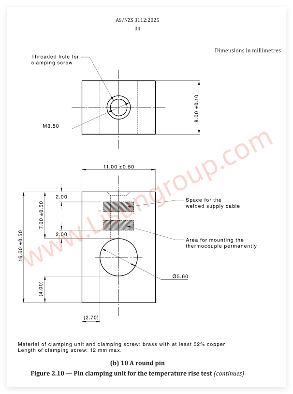
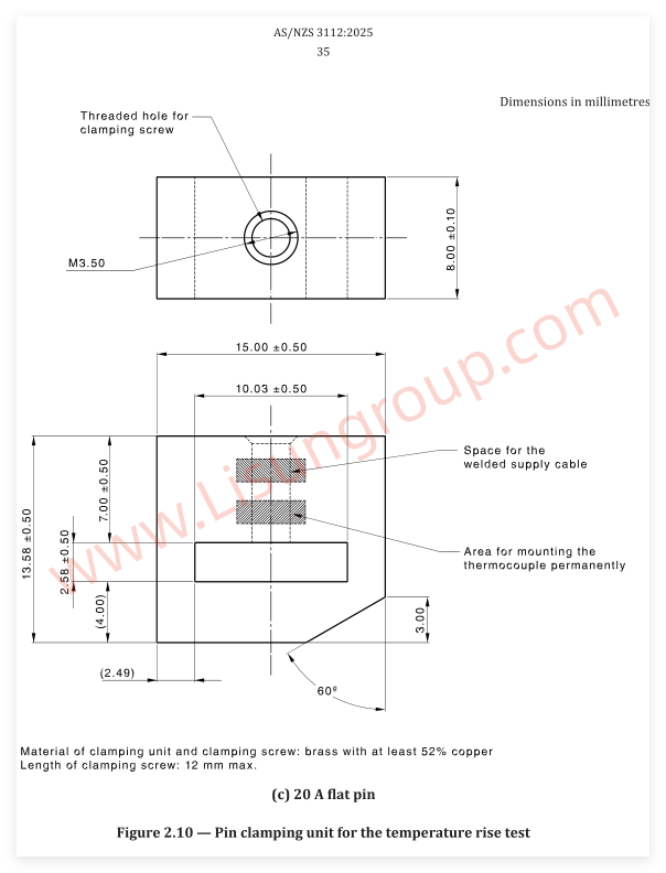
AS/NZS 3112:2025 Clause 2.13.8 Figure 2.10
Tags:GNGPL-31210
 English
 中文简体
中文简体 English
 Русский
 Español
 Português
 Türkçe
 العربية
 Deutsch
 Polski
 Italiano
 Français
 한국어
한국어 ไทย
ไทย Tiếng Việt
 日本語
日本語






