
LM-79 Moving Detector Goniophotometer (Mirror Type C)
LSG-6000

High Precision Rotation Luminaire Goniophotometer
LSG-1890B

High Precision Rotation Luminaire Goniospectroradiometer
LSG-1890BCCD

Goniophotometer for Automotive and Signal Lamps
LSG-1950

Goniophotometer for Traffic Signal Lamps
LSG-1950S

VAD Fire Alarm Visual Alert Device Goniophotometer
LSG-1930

Compact Goniophotometer
LSG-1200A

LED Goniophotometer
LSG-1100
 LEDs and Luminaire Test Solutions
 LM-79 and LM-80 Test Solutions
 LED Driver Test Solutions
 Household Appliances Test Solutions
 Mobile and Network Test Solutions
 Automotive Electronics Test Solutions
 Audio-Video and IT Test Solutions
 Cable and Wire Test Solutions
 Plugs and Sockets Test Solutions
 Power Switch Test Solutions
 Transformer Test Solutions
 Electric Toys Test Solutions
 Energy Meter Test Solutions
 Motor-Operated Tool Test Solutions
Select an organization
to browse standards
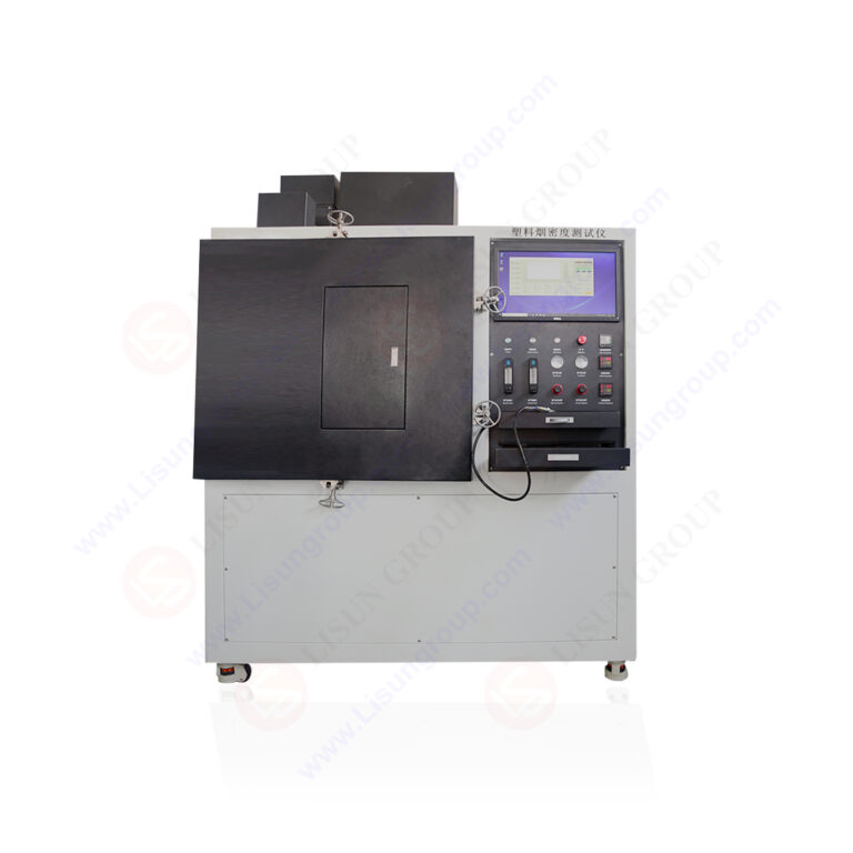

Product No: LS-ISO5659
The LS-ISO5659 Smoke Density Test Chamber, also known as the NBS Smoke Density Chamber, is professional smoke density testing equipment compliant with ISO 5659 standard. Based on the light attenuation detection principle within a sealed cavity, it simulates the thermal decomposition and combustion conditions of materials via a conical radiant heat source. Equipped with a high-precision photoelectric optical system, it accurately measures and calculates key parameters including smoke light transmittance, specific optical density and mass loss rate generated during material combustion. Integrated with a constant-temperature and constant-pressure cavity, controllable radiant heating system, precise air supply and ignition unit, accurate weighing module and intelligent detection unit, the equipment supports both non-flaming thermal decomposition and flaming combustion test modes. Automatic data acquisition and calculation throughout the test effectively reduce manual errors and deliver outstanding testing accuracy and repeatability.
It is widely applied for smoke density measurement of various non-metallic solid materials such as wires and cables, plastics, architectural decorations, rail transit components, aerospace materials and new energy insulation materials. Suitable for product R&D, factory outgoing quality inspection and third-party compliance testing, it fully meets domestic and international fire safety testing specifications.
| System Configuration | Specifications |
| Chamber structure and its pressure and temperature control | 1.Internal dimensions of the test chamber: 914 mm (L) × 914 mm (W) × 610 mm (D). Steel structure construction with inner surfaces coated in Teflon for corrosion protection. |
| 2. The hinge-mounted front door is equipped with a tempered glass viewing window and an openable opaque light shield to block external light. | |
| 3. An explosion relief opening over 80600 mm² is arranged inside the test chamber. The airtight rupture disc is made of ≤0.04 mm thick aluminium foil and protected by stainless steel wire mesh. | |
| 4. A 75 mm diameter optical window is arranged on the top and bottom of the test chamber separately for smoke density testing. | |
| 5. Baffled air inlet and outlet are installed on the top and bottom of the test chamber. | |
| 6. The fully sealed chamber can generate and maintain positive pressure by air intake. Internal pressure is monitored by a differential pressure transmitter ranging from 0 to 2.5 kPa. | |
| 7. Ten U-shaped heating wires are installed on the outer wall of the test chamber to elevate the average temperature. Thermocouples attached to the chamber wall monitor the wall temperature. | |
| Radiating cone device and its control system | 1. The radiant cone assembly is composed of cone housing, heating tubes, temperature measuring thermocouples, shielding layers, ignition device and other parts. |
| 2. The radiant cone housing is made of 1 mm heat-resistant stainless steel. Its outer cover features 45 mm overall height, 55 mm inner diameter and 110 mm base diameter. Thermal insulation is filled between inner and outer cone shells with machined holes for thermocouple mounting. | |
| 3. Three Φ1.5 mm K-type thermocouples are mounted on the cone at 120° intervals to detect heating wire temperature. The cone heat output is controlled via power regulator and temperature measurement module. | |
| 4. The heating element is rated at 2.2 kW, constructed by coiling Φ6.5 mm high-temperature resistant heating tubes into a cone. It delivers radiant heat flux of 10~50 kW/m² to the center of the exposed specimen surface. | |
| 5. The radiant cone is fixed and protected by vertical positioning rods of the support frame. The gap between the cone’s lower edge and the specimen is 25±1 mm, adjustable to 50 mm for intumescent materials. | |
| Igniter and gas supply system | 1. The igniter is fabricated from stainless steel tubing with an outer diameter of 4 mm and an inner diameter of 2 mm. It generates a horizontal flame of 30±5 mm in length. The flame is blue with a yellow tip. |
| 2. The igniter uses automatic high-voltage pulse ignition; ignition voltage: 10 kV. | |
| 3. Gas and air flows are regulated by MFCs. Propane MFC range: 0~100 mL/min; Air MFC range: 0~500 mL/min. | |
| 4. Equipped with solenoid valves and ball valves to shut off gas supply after testing and improve safety. | |
| Sample mounting and weighing system | 1. The specimen mounting assembly comprises specimen holder, positioning frame, adjustable support rods, weighing unit, thermal insulation materials and protective box. |
| 2. Made of 1 mm stainless steel, the square specimen holder features a 78±1 mm opening and 25±1 mm height. A welded handle facilitates access. The bottom has a square groove matching the mounting bracket, and fastening screw holes on both sides avoid vibration-induced dropping during tests. | |
| 3. The specimen positioning frame is constructed from 1 mm stainless steel. It fully covers the specimen holder box, with a 65 mm square opening on top for contact between specimen and heat source. | |
| 4. The stainless steel sleeve-type adjustable support rod is locked by knobs for convenient positioning of standard specimens and specimens with unstable dimensions. The distance from the top of standard specimens to the radiant cone is 25 mm, and 50 mm for dimensionally unstable materials. The lower end of the rod connects to the weighing unit. | |
| 5. Equipped with Siemens weighing module. Weighing range for specimens: 0~3000 g, accuracy: 0.01 g. The integrally installed load cell precisely detects specimen weight and mass loss rate. | |
| 6. The connection between adjustable support rod and load cell is insulated with bakelite. Aluminum silicate insulation inside the protective box above the load cell stabilizes sensor operating temperature and prolongs service life. | |
| Optical path system | 1. The light transmitting and receiving systems are arranged at the top and bottom of the test chamber. Light signals pass through glass sheets hermetically sealed against the chamber. |
| 2. The light transmitting unit uses a 6.5 V incandescent lamp fitted with reflector and convex lens to supply light into the smoke chamber. | |
| 3. The light receiving system is fitted with a Japanese Hamamatsu optical amplifier, which converts received light into signals for main program calculation, accuracy: 0.1%. | |
| 4. Filters mounted at the receiving end calibrate optical signals for better stability. Shading levels of 0, 10%, 50% and 100% can be automatically switched under software control. | |
| Heat flow meter system | 1. Thermopile heat flux gauge, range: 0~100 kW/m². The 12.7 mm diameter radiation receiving target with durable matte black coating is water-cooled. Accuracy: ±3%, repeatability: ±0.5%. Clip-type positioning and screw fastening mechanisms are used for calibration, offering easy operation and precise alignment. |
| 2. The heat flux gauge is fitted with a portable self-contained water cooling system, requiring no external cooling water supply. The control panel shows water temperature and flow status for real-time cooling monitoring. | |
| Control method | 1. Computer-controlled via dedicated software with guided operation; easy, safe and reliable to operate. |
| 2. PLC and modules control component actions and acquire signals. | |
| 3. Automatic data acquisition, calculation, storage and report generation. | |
| 4. Real-time data & smoke density curve display; historical curve and data display & query. |
Tags:LS-ISO5659
Abstract Reduced visibility caused by smoke during fire accidents is a major contributor to...

 English
 中文简体
中文简体 English
 Русский
 Español
 Português
 Türkçe
 العربية
 Deutsch
 Polski
 Italiano
 Français
 한국어
한국어 ไทย
ไทย Tiếng Việt
 日本語
日本語






