
LM-79 Moving Detector Goniophotometer (Mirror Type C)
LSG-6000

High Precision Rotation Luminaire Goniophotometer
LSG-1890B

High Precision Rotation Luminaire Goniospectroradiometer
LSG-1890BCCD

Goniophotometer for Automotive and Signal Lamps
LSG-1950

Goniophotometer for Traffic Signal Lamps (Economical Model)
LSG-1950S

VAD Fire Alarm Visual Alert Device Goniophotometer
LSG-1930
Goniophotometer for Airfield Lighting
LSG-1940

Compact Goniophotometer
LSG-1200A

LED Goniophotometer
LSG-1100
Near Field Moving Detector Goniophotometer
LSG-1900B
 LEDs and Luminaire Test Solutions
 LM-79 and LM-80 Test Solutions
 LED Driver Test Solutions
 Household Appliances Test Solutions
 Mobile and Network Test Solutions
 Automotive Electronics Test Solutions
 Audio-Video and IT Test Solutions
 Cable and Wire Test Solutions
 Plugs and Sockets Test Solutions
 Power Switch Test Solutions
 Transformer Test Solutions
 Electric Toys Test Solutions
 Energy Meter Test Solutions
 Motor-Operated Tool Test Solutions
Select an organization
to browse standards
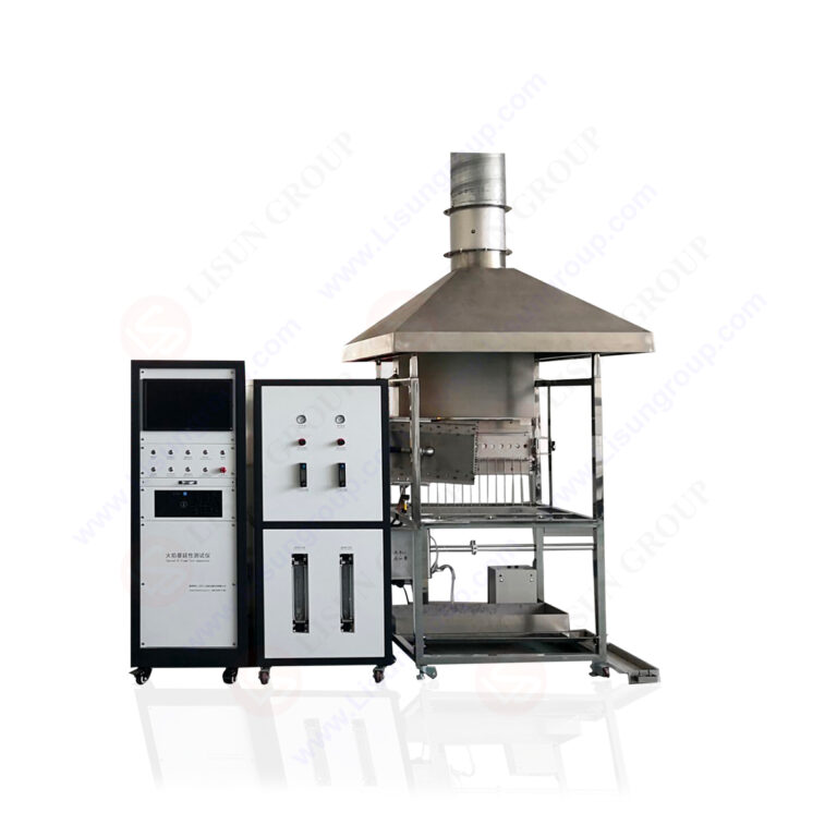

Product No: LS-ISO5658-2
IMO Flame Spread Test Apparatus fully complies with the test requirements of ISO 5658-2, ASTM E1317, GB/T 28752-2012, IMO FTPC Part 5 & 6, IMO Res.653 (16) and other relevant standards. Its testing principle is as follows: under the combined effect of a constant infrared radiant heat source and a standard pilot flame on vertically mounted specimens, the entire process of lateral flame spread is observed to accurately determine key flame retardancy parameters including Critical Flux at Extinction (CFE) and average sustained combustion heat. The complete unit adopts a split stainless steel cabinet paired with a separate control cabinet. Equipped with professional LabVIEW measurement and control software, it integrates automatic heat flux calibration, methane calibration, flame adjustment, data acquisition and report generation in one system. It can automatically complete a full set of compliant tests and avoid data errors caused by manual operation.
IMO Flame Spread Test Apparatus is suitable for testing various specimens including flat homogeneous materials, composite panels and tubular components. It is widely applied to evaluate the flame retardant performance of ship bulkheads, deck floor coverings, rail transit interior materials and vertical building finishing materials. The equipment is standardly equipped with a mobile water-cooled heat flux meter, standard calibration aluminum plate, and dual gas supply circuits for propane and methane. It supports two-level calibration modes: daily inspection and monthly full-point calibration. The software plots real-time curves of radiant heat flux and temperature variation, automatically records the flame spread duration at each node, and generates archiveable standard test reports with one click. It meets the routine testing requirements of third-party marine survey laboratories, material manufacturers, and university flame retardant research laboratories.
System Composition:
• Combustion Chamber Unit: gas collection and exhaust hood, infrared radiant heating panel, stainless steel specimen holder, sliding calibration guide rail, ceramic pilot burner;
• Independent Electrical Control Cabinet: main power switch, emergency stop button, radiant panel ignition control, calibration ignition control, variable frequency exhaust control module;
• Gas Supply System: propane test gas circuit, methane calibration gas circuit, air pressure regulating pipeline, precision rotameter, MFC mass flow controller;
• Calibration Accessories: water-cooled heat flux meter, standard porous calibration aluminum plate, handheld anemometer;
• Measurement & Control Unit: Computer + LISUN customized LabVIEW test software.
Product Advantages:
• Split-type safety layout: The combustion chamber is separated from the electrical control cabinet, keeping electrical components away from high-temperature zones to avoid failures caused by long-term thermal aging. The whole unit is constructed of stainless steel for excellent corrosion resistance and easy cleaning.
• High-precision radiant temperature control system: An imported MFC propane mass flow controller regulates the infrared radiant panel with radiant heat flux accuracy up to 0.1 kW/m². The sliding heat flux meter platform enables full-range multi-point calibration, and the software automatically generates standard heat flux calibration curves.
• Standardized safe ignition system: A ceramic pilot burner with dual precision flow meters accurately controls propane and air intake to deliver a stable standard flame of 230±20 mm. It is equipped with multiple safety protections including high-voltage pulse automatic ignition, flame loss gas cut-off alarm, and explosion-proof solenoid valve.
• Complete standardized calibration kit: Factory-supplied accessories include water-cooled heat flux meter, porous calibration aluminum plate and methane calibration assembly. Daily and monthly hierarchical calibration procedures fully comply with national standards and marine regulations, with fully traceable calibration data.
• Intelligent LabVIEW measurement & control system: Guided operation interface divided into three independent modules: calibration, testing and metrology. It automatically captures the timing of flame spread nodes and calculates core indicators such as Critical Flux at Extinction (CFE) and average sustained combustion heat.
• Laboratory-friendly design: Variable-frequency adjustable exhaust fan precisely controls airflow around specimens ≤0.2 m/s. The machine features standard earthing protection, and gas pipelines are fitted with check valves to prevent flashback, effectively avoiding radio interference affecting test data.
Specifications:
| Flame spread measurement accuracy | 1 mm |
| Radiative heat flux range & accuracy | 1.5~49.5kW/m²,Accuracy: 0.1kW/m² |
| Standard ignition flame | Height 230±20mm; Propane flow rate 24L/min, air flow rate 1.0L/min |
| Test gas | Industrial propane (calorific value 83 MJ/m³) |
| Calibrate gas | Methane with a purity of ≥98% |
| Calibration mode | Daily calibration: 50mm and 350mm (two points); Monthly calibration: 50/150/250/350/450/550/650/750 (all points) |
| Ambient airflow control | The air velocity in the sample area is ≤0.2 m/s. |
| Power supply | AC220V 50Hz |
| Sample fitting | Supports two types of sheet materials: gapless and 25mm standard sandwich panels with gaps. Tubular components are tested with dedicated fixtures. |
| Software Functions | Automatic data acquisition, curve visualization, automatic calculation of CFE/mean continuous heat of combustion, and one-click export of PDF reports. |
Operating Procedures:
Step 1 Pre-test Calibration (Mandatory daily startup procedure)
• Install the calibration plate and water-cooled heat flux meter. Launch the measurement and control software and start the exhaust fan. Adjust the fan frequency, and verify the airflow in the specimen area ≤0.2 m/s using an anemometer.
• Turn on the gas supply and ignite the radiant panel. Maintain thermal equilibrium with a 15-minute soaking period. Perform full-point heat flux calibration from 50 mm to 750 mm sequentially and save the radiant heat flux curve.
• Access the methane calibration interface. Collect reference temperatures corresponding to methane power levels of 1 kW, 3 kW, 5 kW, 7 kW and 9 kW to complete temperature baseline calibration.
• Adjust the pilot flame: regulate gas pressure and flow rate, calibrate flame height and standard specimen clearance, ensuring the flame covers half of the specimen height.
Step 2 Specimen Preparation and Mounting
• Draw a centerline along the length on the specimen surface and mark scales every 50 mm. Differentiate specimens with gaps and specimens without gaps, then secure them with standard aluminum backplates and positioning tabs.
• Mount the assembled specimen into the holder. The entire mounting operation shall be completed within 15 seconds.
Step 3 Formal Combustion Test
• Confirm that the radiant panel maintains thermal equilibrium and the pilot flame adjustment is finished. Click Test in the software to enter the test interface.
• After specimen mounting is completed, click Start to begin timing.
• When the flame front reaches the scale marks of 50, 150, 250…750 mm, click the corresponding scale buttons sequentially. The system automatically records the flame spread duration.
• Once any termination condition is satisfied, including no ignition within 10 minutes, flame stagnation, or flame reaching the end of the specimen, click Stop to terminate the test. Save data and generate the test report.
Step 4 Specification for Replicate Tests
• For non-anisotropic materials, conduct 3 sets of tests in a single direction and take the average value.
• For anisotropic specimens, perform additional replicate tests in the perpendicular direction; calculate results after eliminating extreme values.
• Supplementary replicate tests shall be carried out in accordance with standards under conditions such as specimen non-ignition, incomplete combustion or heavy smoke generation.

 English
 中文简体
中文简体 English
 Русский
 Español
 Português
 Türkçe
 العربية
 Deutsch
 Polski
 Italiano
 Français
 한국어
한국어 ไทย
ไทย Tiếng Việt
 日本語
日本語






