
LM-79 Moving Detector Goniophotometer (Mirror Type C)
LSG-6000

High Precision Rotation Luminaire Goniophotometer
LSG-1890B

High Precision Rotation Luminaire Goniospectroradiometer
LSG-1890BCCD

Goniophotometer for Automotive and Signal Lamps
LSG-1950

Goniophotometer for Traffic Signal Lamps
LSG-1950S

Compact Goniophotometer
LSG-1200A

Near Field Moving Detector Goniophotometer
LSG-1900B
Select an organization
to browse standards
Digital oscilloscopes have become indispensable instruments in modern electronic testing and measurement, enabling engineers to capture, analyze, and interpret electrical signals with unprecedented precision and flexibility. This comprehensive technical article explores the fundamental principles, key specifications, and engineering applications of digital oscilloscopes, with particular focus on the OSP1102 model featuring 100 MHz bandwidth and 1 GS/s sample rate.
Through detailed examination of critical performance parameters including bandwidth, sample rate, vertical resolution, and triggering capabilities, this analysis provides engineers and researchers with practical insights for selecting and utilizing oscilloscopes in various testing scenarios. The discussion encompasses signal acquisition methodologies, measurement accuracy considerations, and the technical trade-offs inherent in different instrument configurations, offering a systematic framework for understanding oscilloscope functionality in both research and industrial environments.
The evolution of electronic measurement instrumentation has fundamentally transformed how engineers analyze and troubleshoot electrical circuits and systems. Since their inception in the early 20th century, oscilloscopes have progressed from basic cathode ray tube (CRT) displays to sophisticated digital acquisition systems capable of capturing transient events with nanosecond precision. The transition from analog to digital technology represents one of the most significant advancements in test and measurement equipment, enabling capabilities that were previously impossible with traditional instruments.
This article aims to provide a comprehensive technical analysis of digital oscilloscopes, examining the critical specifications that determine measurement performance and suitability for various applications. By exploring the interrelationship between bandwidth, sample rate, and vertical resolution, this analysis offers engineers a systematic approach to instrument selection and optimization. Particular attention is given to the technical requirements for accurate signal reconstruction, the importance of triggering systems in waveform capture, and the practical considerations for applying oscilloscopes in electronic product development and quality assurance processes. Understanding these fundamental principles is essential for maximizing the utility of the digital oscilloscope in modern engineering practice.
Unlike their analog predecessors, digital oscilloscopes employ a fundamentally different approach to signal acquisition and display. The input signal passes through an analog front-end circuit before reaching the analog-to-digital converter (ADC), which samples the continuous waveform at discrete time intervals. Each sample is quantized into a digital value and stored in memory, enabling sophisticated post-acquisition analysis and measurement. This architecture allows for advanced features such as waveform storage, automatic measurements, and mathematical operations that were impractical or impossible with analog instruments.
The signal acquisition process in digital oscilloscopes involves several critical stages that collectively determine measurement accuracy and fidelity. The input attenuator and amplifier stage conditions the signal to match the ADC’s input range, while the sampler and ADC convert the analog voltage into digital values at rates determined by the timebase system. Modern oscilloscopes utilize sophisticated triggering mechanisms to capture specific events of interest, storing the digitized waveform in memory for subsequent display and analysis. This process enables single-shot acquisition of non-repetitive signals, a capability that distinguishes digital oscilloscopes from their analog counterparts.
Bandwidth represents the most fundamental specification of any oscilloscope, defining the frequency range over which the instrument can accurately measure signals. Technically, bandwidth is specified as the frequency at which a sinusoidal input signal is attenuated to 70.7% of its original amplitude, corresponding to the -3 dB point. This attenuation characteristic arises from the combined frequency response of the input attenuator, amplifier, and other analog front-end components. For the OSP1102 with 100 MHz bandwidth, signals at this frequency will display approximately 30% amplitude reduction, while lower frequencies exhibit progressively less attenuation.
The relationship between bandwidth and measurement accuracy carries significant implications for practical applications. Industry guidelines recommend selecting an oscilloscope with bandwidth at least 3-5 times higher than the highest frequency component of interest. For digital signals, this becomes particularly critical because square waves and pulses contain harmonic content extending well beyond their fundamental frequency. A 100 MHz digital clock signal, for instance, contains significant energy at the 5th harmonic (500 MHz) and beyond, necessitating an oscilloscope with substantially higher bandwidth to accurately capture the signal’s true shape and transition characteristics.
While bandwidth determines the frequency range an oscilloscope can measure, sample rate governs the temporal resolution with which signals are captured. The sample rate, expressed in samples per second (S/s), defines how frequently the ADC converts the analog input into digital values. According to the Nyquist-Shannon sampling theorem, a signal must be sampled at least twice its highest frequency component to avoid aliasing and enable accurate reconstruction. However, this theoretical minimum proves insufficient for practical time-domain measurements.
Industry best practices recommend a sample rate 3-4 times the oscilloscope’s bandwidth to achieve accurate waveform reconstruction. For the OSP1102’s 100 MHz bandwidth, the 1 GS/s sample rate provides a 10:1 ratio, substantially exceeding this guideline and ensuring excellent signal fidelity. This oversampling approach provides multiple sample points across each period of the input signal, enabling accurate measurement of rise time, pulse width, and other time-domain parameters. Insufficient sample rate results in undersampling, which distorts the reconstructed waveform and leads to measurement errors.
Vertical resolution, determined by the ADC’s bit count, defines the smallest voltage change an oscilloscope can theoretically detect. An 8-bit ADC, as used in the OSP1102, divides the input range into 256 discrete levels, while higher resolution instruments offer finer granularity. The resolution directly impacts the instrument’s ability to distinguish small signal variations and measure signals with large amplitude differences. For a 10 V input range, an 8-bit oscilloscope provides approximately 39 mV resolution, whereas a 14-bit instrument would offer 0.61 mV resolution.
The relationship between resolution and measurement accuracy extends beyond simple voltage granularity. Higher resolution instruments offer improved dynamic range, enabling measurement of small signals in the presence of larger signal components without clipping or noise masking. This capability proves essential for applications involving amplitude-modulated signals, power supply ripple measurements, and other scenarios where signal components span wide amplitude ranges. However, resolution improvements typically involve trade-offs in sample rate and cost, requiring careful consideration of application requirements.
The OSP series digital oscilloscopes encompass a range of models designed to address various testing requirements, from basic educational applications to advanced electronic product development. Table 1 presents a comparative analysis of key specifications across different models, illustrating the progression of capabilities and typical application scenarios. The OSP1102, with its 100 MHz bandwidth and 1 GS/s sample rate, serves general-purpose electronic testing applications including microcontroller debugging, power supply characterization, and communication signal analysis.
Table 1: Technical Specifications Comparison of OSP Series Digital Oscilloscopes
| Model | Channels | Bandwidth | Sample Rate | Resolution | Display |
| OSP1102 | 2 | 100 MHz | 1 GS/s | 8 bits | 7 inch |
| OSP3202E | 2 | 200 MHz | 1 GS/s | 8 bits | 8 inch |
| OSP3302 | 2 | 300 MHz | 2.5 GS/s | 8 bits | 8 inch |
| OSP3202A | 2 | 200 MHz | 2.5 GS/s | 14 bits | 8 inch |
The relationship between bandwidth and rise time represents a fundamental consideration in oscilloscope selection and measurement interpretation. Rise time, defined as the time required for a signal to transition from 10% to 90% of its amplitude, correlates directly with bandwidth through the approximation: Rise Time = 0.35/Bandwidth. This relationship enables engineers to estimate the fastest edge an oscilloscope can accurately capture and predict the measurement error when the instrument’s rise time approaches the signal’s rise time.
Table 2 illustrates the calculated rise times for various bandwidth specifications and provides guidance on signal rise time measurement accuracy. When measuring signals with rise times approaching the oscilloscope’s own rise time capability, the displayed rise time will be a combination of the actual signal rise time and the instrument’s response. Engineers must account for this effect when characterizing fast signals, using the formula: measured rise time² = actual signal rise time² + oscilloscope rise time² to extract the true signal characteristics from measurements.
Table 2: Bandwidth-Rise Time Relationship and Measurement Accuracy Guidelines
| Bandwidth | Rise Time | Recommended Signal Rise Time | Measurement Accuracy |
| 100 MHz | 3.5 ns | >17.5 ns (5x rule) | ±2% |
| 200 MHz | 1.75 ns | >8.75 ns (5x rule) | ±2% |
| 300 MHz | 1.17 ns | >5.85 ns (5x rule) | ±2% |
The triggering system represents one of the most critical components of a digital oscilloscope, enabling stable display of repetitive waveforms and capture of specific signal events. The trigger circuit monitors the input signal and initiates waveform acquisition when predefined conditions are met. Basic edge triggering, the most common trigger type, activates when the signal crosses a specified voltage threshold with a defined slope (rising or falling). More advanced trigger types include pulse width triggering, which responds to pulses of specific duration, and pattern triggering for digital signals.
Modern digital oscilloscopes offer sophisticated triggering options that extend far beyond simple edge detection. These advanced capabilities enable engineers to isolate specific signal conditions that might otherwise be difficult to capture, such as glitches, runt pulses, setup and hold violations, and specific serial data patterns. The trigger system’s sensitivity and accuracy directly impact the oscilloscope’s ability to capture elusive signal anomalies. For the OSP1102 and similar instruments, the trigger sensitivity typically ranges from 0.5 divisions for DC-coupled signals to slightly higher values for AC-coupled inputs, ensuring reliable triggering across a wide range of signal amplitudes and frequencies.

Digital oscilloscopes provide extensive automated measurement capabilities that streamline waveform analysis and reduce the potential for human error in manual measurements. Standard measurements include voltage parameters (peak-to-peak, maximum, minimum, average, RMS), timing parameters (period, frequency, rise time, fall time, pulse width, duty cycle), and derived parameters such as overshoot and undershoot. These measurements execute in real-time, updating continuously as new waveform data is acquired, enabling engineers to monitor signal characteristics during circuit adjustment and optimization.
Beyond basic measurements, modern oscilloscopes incorporate advanced analysis functions including Fast Fourier Transform (FFT) for frequency domain analysis, mathematical operations on waveforms (addition, subtraction, multiplication, division), and statistical analysis of measurement trends. FFT capability transforms time-domain waveforms into the frequency domain, revealing harmonic content, identifying noise sources, and enabling analysis of modulation characteristics. These analysis tools transform the oscilloscope from a simple visualization instrument into a comprehensive signal analysis platform, supporting complex debugging and characterization tasks.
Selecting an appropriate oscilloscope requires careful consideration of application requirements, budget constraints, and future needs. The primary specification criteria include bandwidth (sufficient for the highest frequency signals), sample rate (adequate for accurate signal reconstruction), vertical resolution (matching the required measurement precision), and number of channels (accommodating all signals requiring simultaneous observation). Additional considerations include memory depth for capturing long time windows, trigger capabilities for isolating specific events, and analysis features supporting the intended measurement tasks.
The OSP1102, with its 100 MHz bandwidth and dual-channel configuration, addresses a broad range of testing applications in electronics development and manufacturing. Typical applications include microcontroller-based system debugging, where 8-bit microcontrollers operate at clock frequencies well within the instrument’s bandwidth; power supply characterization, enabling measurement of switching frequencies, output ripple, and transient response; and communication signal analysis for protocols operating at moderate data rates. The instrument’s combination of adequate bandwidth, sufficient sample rate, and comprehensive measurement capabilities makes it suitable for educational environments, research laboratories, and quality assurance applications.
Digital oscilloscopes represent fundamental tools in modern electronic engineering, providing essential capabilities for signal visualization, measurement, and analysis. Through comprehensive examination of critical specifications including bandwidth, sample rate, and vertical resolution, this analysis has demonstrated the technical considerations governing oscilloscope performance and application suitability. The OSP1102, with its 100 MHz bandwidth and 1 GS/s sample rate, exemplifies a general-purpose instrument suitable for diverse electronic testing applications, from educational environments to industrial quality assurance.
Understanding the interrelationship between these specifications enables engineers to make informed selection decisions and optimize measurement accuracy. As electronic systems continue to increase in complexity and speed, the digital oscilloscope remains an indispensable instrument for circuit development, debugging, and validation, with ongoing technological advances expanding measurement capabilities and analysis functionality.
Tags:OSP1102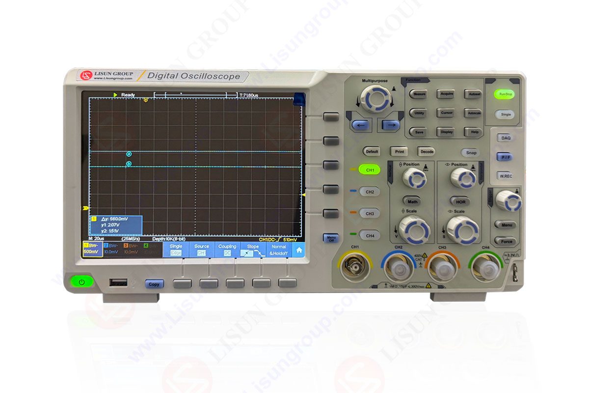

 中文简体
中文简体