LM-79 Moving Detector Goniophotometer (Mirror Type C)
LSG-6000

High Precision Rotation Luminaire Goniophotometer
LSG-1890B

High Precision Rotation Luminaire Goniospectroradiometer
LSG-1890BCCD

Goniophotometer for Automotive and Signal Lamps
LSG-1950

Goniophotometer for Traffic Signal Lamps
LSG-1950S

Compact Goniophotometer
LSG-1200A

Near Field Moving Detector Goniophotometer
LSG-1900B
Select an organization
to browse standards
The same flush and self-contained receptacle having a 5-15R,5-20R,6-15R,or 6-20R configuration used for the conductor insertion and retention test and the conductor push-in test are to be tested as described in this section. The test conductors used in the previous tests are to be removed from the receptacles using the wire release mechanism.
Exception: For receptacles without a wire release mechanism, previously untested receptacles are to be used.
As a result of the test described in 136.3, there shall not be any breakage or distortion of the insulating body of the receptacle that:
a) Would expose live parts to contact by a 1/32 inch (0.79 mm) diameter rod, or
b) Results in reduction of electrical spacings to values less than those required for the receptacle.
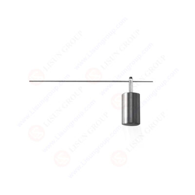
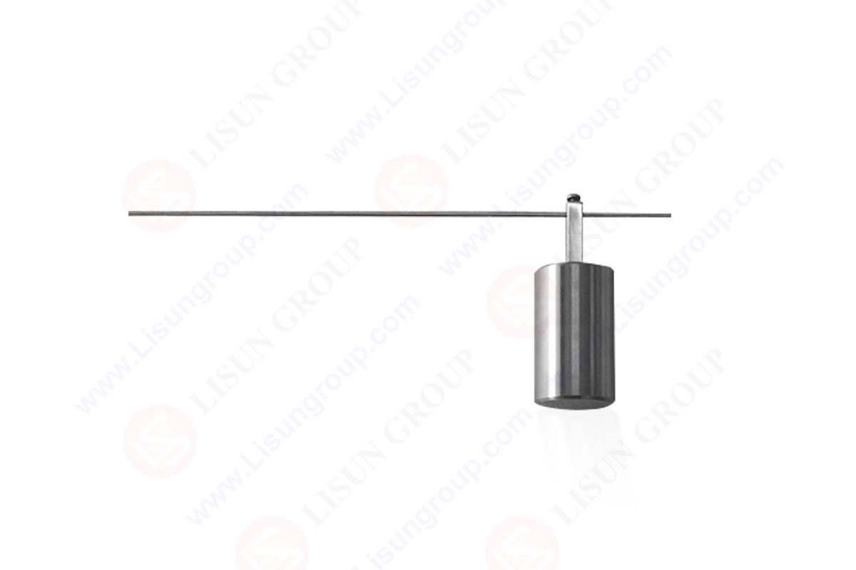
Each receptacle is to be mounted in the test fixture shown in Figure 136.1 with its face in a vertical plane. The test pin shown in Figure 136.2 is then to be fully inserted into the “Push-In” terminal opening. An 8-ounce (0.23-kg) weight is to be gradually suspended from the test pin 6 inches(152 mm) from the plane of the terminal opening. The weight is to be applied for one minute, following which the weight is to be removed. The application of the weight is to be repeated with the receptacle rotated 90,180 and 270degrees for a total of four applications per receptacle.

14 AWG Test Pin of UL 498:2017 Figure 136.2

 中文简体
中文简体