
 English
 中文简体
中文简体 English
 Русский
 Español
 Português
 Türkçe
 العربية
 Deutsch
 Polski
 Italiano
 Français
 한국어
한국어 ไทย
ไทย Tiếng Việt
 日本語
日本語





























Leakage Current Tester
User's Manual
Applicable LISUN models: WB2675A、WB2675B、WB2675C、WB2675D
1. Unboxing and Basic Familiarization with the Equipment
1.1 Key Technical Specifications
| Specifications/Model Numbers | WB2675A | WB2675B | WB2675C | WB2675D |
| Test Current Range | 0–2 mA/20 mA | |||
| Accuracy | ±5% | |||
| Test Time | 1–99 seconds (timer/manual dual modes) | |||
| Isolation Transformer Capacity | 500 VA | 1000 VA | 2000 VA | 5000 VA |
1.2 Unboxing and Checking the Contents
1.2.1 Unpacking and Visual Inspection
When unpacking the device, handle it gently to avoid scratching the casing with sharp tools. After unpacking, first inspect the exterior of the device to ensure there is no visible deformation or dents, and that the buttons are not damaged or loose. If you notice any abnormalities with the device or its accessories, do not turn it on. Please contact us immediately.
1.2.2 Host and Accessories
Host: 1 WB2675 host.
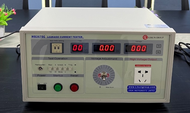
Figure 1
The main components are as follows:
| Number | Note |
| ① | Power Cord |
| ② | Test Input Power Supply Cable |
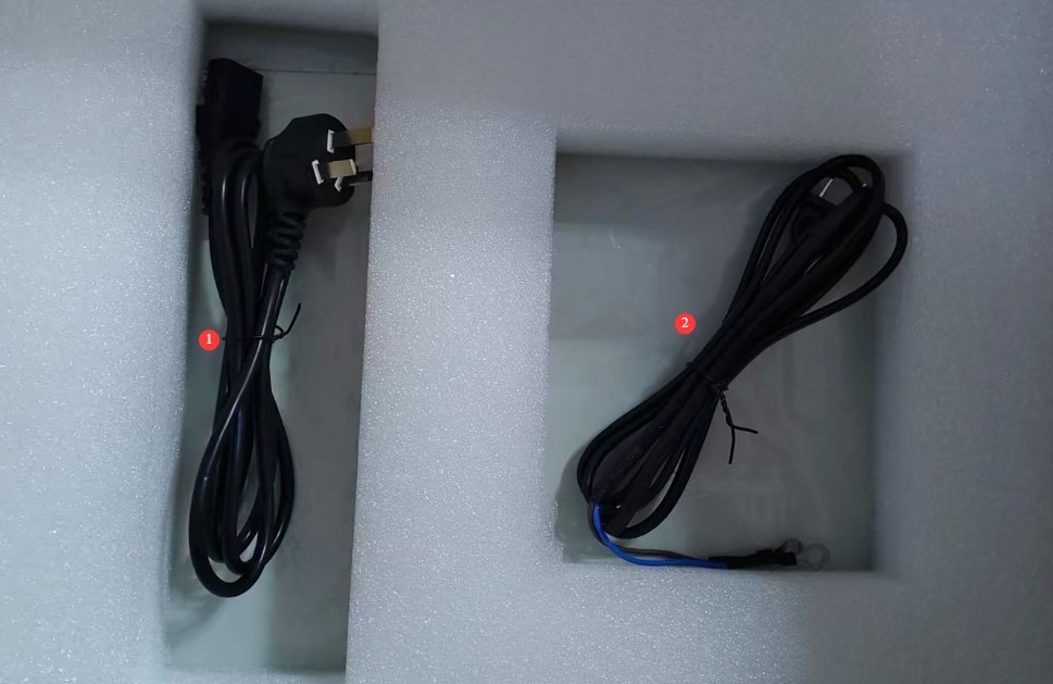
Figure 2
Download links for the digital user manual, software, warranty card, and other materials have been sent via email. Please download them as soon as possible. If you missed the email, please feel free to contact us to obtain the download links again.
2 Safety Precautions
2.1 Electrical Safety
2.1.1 Power Requirements
Use a single-phase AC 220 V ±10%, 50/60 Hz three-prong outlet; the ground prong must be connected to ground.
2.1.2 Grounding Requirements
The instrument ground wire is reliably connected to the protective ground wire, and the protective grounding resistance is ≤4 Ω.
2.2 Environmental Safety
2.2.1 Temperature and Humidity Requirements
Avoid using this device in environments where humidity exceeds 70% (without condensation) or where the temperature is outside the range of 0–35°C. The optimal operating temperature is 25±2°C.
2.2.2 Environmental Contraindications
Environments with strong magnetic fields and strong electric fields;
Environments containing corrosive gases or liquids;
Areas with flammable and explosive dust, and areas containing hazardous materials;
Environments with heavy dust, high temperatures and humidity, and direct sunlight.
2.3 Operational Safety
During testing, the housing of the test object is electrically charged; do not touch it with your bare hands under any circumstances;
The test specimen must be placed on a rubber insulating mat;
Operators must wear rubber insulated gloves;
Operators must have dry hands and must not wear any metal jewelry; eating or drinking is prohibited during testing to prevent accidents caused by electric shock;
Before replacing the test item, you must first stop the test and disconnect the test item from the input power supply;
When multiple people are involved, clearly define roles and responsibilities, and confirm them with each other before starting the test to avoid errors.
2.4 Other
For matters not covered in this manual, please proceed with caution or contact us.
3. Equipment Overview and Wiring
3.1 Equipment Front Panel
| Number | Note |
| ① | Power Switch |
| ② | Test Duration Settings: Test durations can be set from 1 to 99 seconds for use with a timer switch. |
| ③ | Test time display, unit: s. Note: Available only when the timer switch is enabled. |
| ④ | Leakage current display, in mA |
| ⑤ | Voltage display for the test object, in V |
| ⑥ | Test Status Indicator: TE: Testing; NG: Leakage current of the test object exceeds the limit + buzzer sounds |
| ⑦ | Leakage current alarm threshold adjustment knob. Note: This setting can only be adjusted in “Preset” mode. |
| ⑧ | Preset/Test Switch: Press to set the alarm value; push out to enter test mode. |
| ⑨ | Range selection: Press to select the 2 mA range; push out to select the 20 mA range. |
| ⑩ | Automatic/Manual Phase Change: Press to switch to automatic 2-second phase change; release to switch to manual phase change. |
| ⑪ | Phase Switching: Switching Between Live and Neutral Wires in Manual Mode |
| ⑫ | Timer switch: Press to enable the timer; release to end the test manually. |
| ⑬ | Voltage adjustment: Adjusts the output test voltage. Depending on the capacity of the Isolation Transformer, the adjustment method may be a knob (turning clockwise increases the voltage; turning counterclockwise decreases the voltage) or a toggle switch (moving to the left gradually decreases the voltage; moving to the right gradually increases the voltage; returning to the center keeps the voltage constant). |
| ⑭ | Socket, used to connect the test object |
| ⑮ | Press the Start button to begin the test; the test light will turn on. |
| ⑯ | Reset button: Cut off output, stop testing, clear alarm |
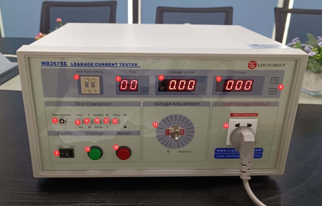
Figure 3
3.2 Equipment Back Panel
| Number | Note |
| ① | Power cord jack, with a 0.5A fuse |
| ② | The input power supply must be connected to a 220 V AC ±10%, 50/60 Hz power source. Before beginning the formal test, set the test voltage to the desired value using the front panel controls. |
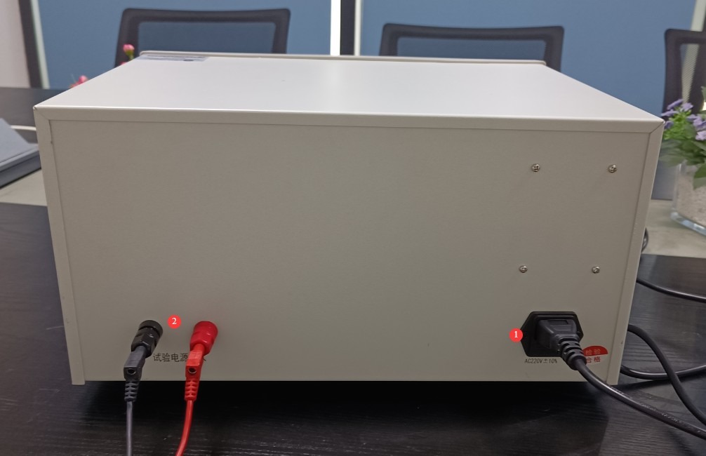
Figure 4
4. Preparations Before Testing
4.1 Instrument Power-On Self-Test
Connect the power supply and turn on the power switch; check that the display is fully illuminated, the indicator lights are functioning normally, and there are no alarms; a no-load current reading of 2–3 digits is normal and does not require calibration.
4.2 Test Parameter Presets
Switch to the preset mode > Select the desired range (2 mA/20 mA) > Adjust the leakage current alarm setting knob to set the alarm threshold > Select the phase-switching mode (Auto/Manual) > Select whether to use a timer; if so, set the desired test duration > Once setup is complete, switch to test mode.
4.3 Test Voltage Presetting
Without connecting the test object—that is, in the no-load test state—press the Start button and check the displayed test voltage. Use the voltage adjustment control to set the test voltage to meet the standard requirements. Once adjusted, press the Reset button.
4.4 Preparation of the Test Specimen
The test object’s housing must be clean and free of oil; place it in the center of the insulated mat, away from the metal work surface, and plug its power cord into the socket on the front panel of the equipment. If the device under test has a power switch, set it to the specified state in accordance with the applicable product test standards; unless otherwise specified, turn on the device’s power switch to put it into normal operating mode.
5. Test Procedure
5.1 Detailed Instructions for the Three Test Modes
5.1.1 Manual Testing (Single-Point Precision Testing)
Set the timer switch to “Off” > Press the Start button; the test light turns on > Press the Phase button to switch between phases and read the leakage current for both phases > After testing, press the Reset button; the test light turns off
5.1.2 Timed Test (Standard Duration Test)
Set the timer switch to “ON,” set the test time (e.g., 5 seconds) > press the Start button > the countdown begins > when the timer ends, the power automatically shuts off; press the Reset button
5.1.3 Automated Testing (High-Throughput Testing)
Set the Auto/Manual button to Auto > Schedule to turn on as needed; press the Start button > The instrument automatically switches phases every 2 seconds and monitors the entire process > Press the Reset button when the test is complete
5.2 Pass/Fail Determination
5.2.1 Conformity Assessment
No alarms were triggered throughout the test, and the current remained below the alarm threshold.
5.2.2 Handling of Nonconformities
The NG alarm light comes on, the buzzer sounds, and power is automatically cut off; the result is recorded as a failure; press the reset button to clear the alarm; do not touch the test item; disconnect the wires before inspecting it.
5.3 Test Wrap-Up Process
Press the reset button; the test voltage will return to 0 and the test light will turn off. Unplug the device under test. If no further testing is required, turn off the instrument and unplug the Input power supply.
6. Daily Maintenance and Care of Equipment
6.1 Routine Maintenance
Before turning on the equipment, check to ensure that the exterior is clean and free of damage, that the cables show no signs of aging or breakage, and that the connectors are secure. After testing is complete, turn off the power and wipe down the equipment surface and the test area with an anti-static, dry cloth.
6.2 Long-Term Storage
When the device is not in use for an extended period, store it in a dry, well-ventilated area, away from moisture and direct sunlight; disconnect all cables, store accessories separately, and cover the device with a dust-proof cloth; turn on the device for 30 minutes each month to prevent the internal electronic components from deteriorating.
7. Troubleshooting and Resolving Common Problems
| Fault Symptoms | Possible Causes | Procedure |
| The device won’t turn on | Blown fuse | Check the fuse in the equipment’s input power supply port. If it is blown, replace it with a 0.5A fuse of the same model. |
| Abnormal Test Voltage | Voltage adjustment is incomplete | Before the formal test, refer to Section 4.3 to pre-adjust the test voltage. |
| Abnormal leakage current display; no alarm when the value exceeds the limit | Incorrect range selection | Refer to Section 4.2. Before testing, ensure that the correct range is selected and the correct alarm thresholds are set. |
Appendix: Table of Common Standard Test Requirements for Leakage and Contact Currents
| Standard Number (Latest Edition) | Scope of Applicable Products | Test Voltage | Touch/Leakage Current Limits (AC) | Recommended Test Time | Recommended Testing Methods |
| GB 4706.1-2020 (equivalent to IEC 60335-1:2020) | Various household appliances (refrigerators, washing machines, microwaves, electric hot pots, small appliances, etc.) | 1.06 times the rated voltage | Class I (with grounding): ≤0.75 mA; Class II (double insulation): ≤0.25 mA; Large, stationary household appliances: ≤3.5 mA | 5s | Automatic phase switching (every 2 seconds) or manual phase switching for dual-side measurement |
| GB 7000.1-2023 (equivalent to IEC 60598-1:2021) | Various types of lighting fixtures (fixed, portable, recessed, LED fixtures, stage lights, etc.) | Class I (with grounding): ≤0.5 mA; Class II (double insulation): ≤0.25 mA; Protective conductor current: ≤3.5 mA (rated current ≤16 A) | Automatic Phase Change (Priority) | ||
| GB 4943.1-2022 (Safety of Information Technology Equipment) | Computers, printers, power adapters, office electronics, and IT-related end-user products | Current on accessible parts: ≤0.25 mA (AC)/≤0.75 mA (DC); Current in the protective conductor: ≤3.5 mA (rated current ≤16 A) | Manual Testing / Scheduled Testing | ||
| GB 9706.1-2020 (equivalent to IEC 60601-1:2012) | Various types of medical electrical equipment (patient monitors, electrocardiographs, electrosurgical units, medical support equipment, etc.) | Normal condition: rated voltage; single-fault condition: 1.06 times the rated voltage | Contact current (casing): Normal ≤ 0.1 mA / Fault ≤ 0.5 mA; Patient leakage current: Normal ≤ 0.1 mA / Fault ≤ 0.5 mA; CF-type cardiac devices: Normal ≤ 0.01 mA | 10 seconds | Precise Manual Testing (State-by-State Testing) |
| IEC 61010-1:2020 (equivalent to GB/T 42125.1-2024 in China) | Electronic Equipment for Measurement, Control, and Laboratory Use | 1.06 times the rated voltage | Class I: ≤0.5 mA; Class II: ≤0.25 mA; CAT III/IV high-protection equipment: ≤0.25 mA | 5s | Automatic Phase-Switching Test |