
 English
 中文简体
中文简体 English
 Русский
 Español
 Português
 Türkçe
 العربية
 Deutsch
 Polski
 Italiano
 Français
 한국어
한국어 ไทย
ไทย Tiếng Việt
 日本語
日本語





























Screwed Glands Torque Test Device
User's Manual
Applicable LISUN models: LWMF-1
1. Unboxing and Basic Familiarization with the Equipment
1.1 Key Technical Specifications
| LISUN Model | LWMF-1 | LWMF-2 |
| Operating Instructions | Electric Lift (Test Duration: Configurable from 0 to 59 minutes, 59 seconds) | Manual Operation |
| Disc Diameter | 500 mm | |
| Specimen Clamping | Chuck-type on both sides, fixed at the disc, with adjustable clamping at the other end | |
| Metal Rod Specifications | Φ6–21, 1 mm intervals | |
| Weights | 2.5 Nm, 3.75 Nm, 4.0 Nm, 5.0 Nm, 6.25 Nm, 7.5 Nm, 10.0 Nm | |
1.2 Unboxing and Checking the Contents
1.2.1 Unpacking and Visual Inspection
When unpacking the device, handle it gently to avoid scratching the outer casing with sharp tools. After unpacking, first inspect the exterior of the device to ensure there are no visible deformations or dents and that the buttons are not damaged or loose.
If you notice any damage or deformation to the equipment or accessories, do not turn on the power. Please contact us immediately.
1.2.2 Main Unit and Accessories
Main unit of the threaded seal cap test apparatus: 1 unit.
The standard accessories are as follows: ① Weights; ② Test rods; ③ Spare parts for the three-jaw chuck.
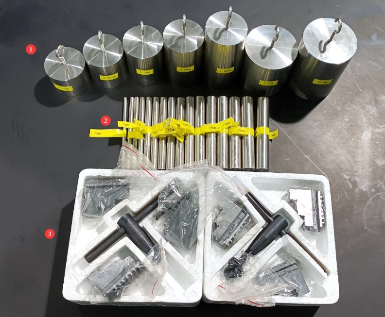
Figure 1
Download links for the digital user manual, warranty card, and other documents have been sent to you via email. Please download them as soon as possible. If you missed the email, please feel free to contact us to request the download links again.
1.3 Description of Equipment Structure
① 500 mm test disc; ② Two sets of three-jaw chucks for securing the threaded seal cap; ③ Electric lift table;④ Power switch; ⑤ Timer—the top line displays the current test duration, and the bottom line displays the set duration; ⑥ Test count setting—the top line displays the current test count, and the bottom line displays the set count; ⑦ Start test; ⑧ Stop test; ⑨ Reset button.
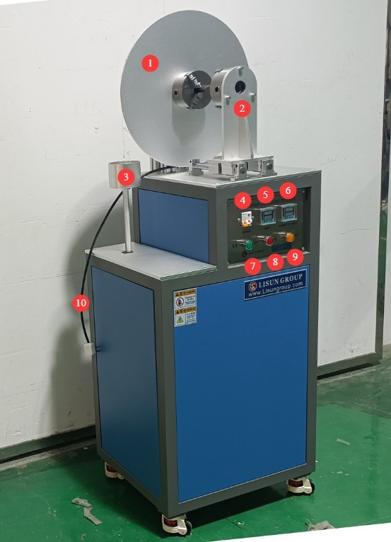
Figure 2
2. Safety Precautions
2.1 Electrical Safety
2.1.1 Power Connection
220V single-phase power; power outlets must comply with safety standards, have proper grounding, and have a rated current that matches the equipment’s power rating.
2.1.2 Grounding Specifications
The equipment must be reliably grounded, with a grounding resistance of ≤4 Ω. Do not use gas pipes, non-metallic water pipes, or the neutral wire as a substitute for the grounding wire. After grounding is complete, use a Grounding Resistance Tester to measure the grounding resistance. Power may only be applied after confirming that the resistance meets the requirements, to prevent electric shock, equipment malfunctions, or measurement errors caused by poor grounding.
2.2 Operational Safety
Before wiring, inspecting, or maintaining equipment, you must turn off the equipment’s power switch and the main power supply, and confirm that there is no residual voltage before proceeding;
Do not operate the equipment’s power switch, touchscreen, or instrument buttons with wet hands to avoid the risk of electric shock;
Do not place any foreign objects (such as tools or paper) inside the electrical control cabinet to prevent dust or foreign objects from causing short circuits or damaging components;
Do not plug in or unplug power cords or signal cables while the equipment is running to prevent short circuits that could damage the controller or electrical components.
2.3 Environmental Safety
The equipment should be placed in a dry environment free of corrosive gases and flammable or explosive materials.
The equipment must be installed in an air-conditioned room, where the ambient temperature is maintained between 5°C and 35°C and the relative humidity is ≤85%.
The distance between the equipment and walls, as well as surrounding structures (such as other testing equipment and shelving), must be at least 1000 mm to facilitate maintenance; at least 2000 mm of space must be left in front of the equipment to ensure smooth operation and keep the surrounding area free of obstructions;
The equipment must be placed on a level, sturdy surface; the height of the equipment’s legs is adjustable.
2.4 Other
For matters not covered in this manual, please proceed with caution or contact us.
3. Preparations Before the Test
3.1 Selection of Test Sticks
When installing the test probe, select a size that matches the inner diameter of the O-ring (slightly smaller and the nearest whole number) to prevent abnormal force transmission caused by the probe being too loose or too tight.
3.2 Selection of Weights
| Applicable Standards | Test Rod Diameter (mm) | Metal Gland Torque (N·m) | Molded Plastic/Insulation Material Cap Torque (N·m) |
| GB/T 7000.1-2023 | <7 | 4.00 | 2.50 |
| >7–14 | June 25 | 3.25 | |
| >14–20 | 7.50 | 5.00 | |
| >20 | 10:00 | 7.50 | |
| GB/T 2099.1-2023 | ≤14 | June 25 | 3.75 |
| >14–20 | 7.50 | 5.00 | |
| >20 | 10:00 | 7.50 | |
| GB/T 15092.1-2020 | ≤14 | June 25 | 3.75 |
| >14–20 | 7.50 | 5.00 | |
| >20 | 10:00 | 7.50 | |
| GB/T 16915.1-2024 | ≤14 | June 25 | 3.75 |
| >14–20 | 7.50 | 5.00 | |
| >20 | 10:00 | 7.50 |
4. Test Procedure for Threaded Sealing Gland
4.1 Test Parameter Settings
Turn on the device. Set the test duration to 60 seconds in accordance with the standard requirements; set the number of tests to 1.
Note: The device’s factory settings have been configured according to the above requirements. Users may also reconfigure the settings to suit their own needs.
4.2 Installing the Sample
Insert the test rod through the sample and tighten it securely to ensure there is no play.
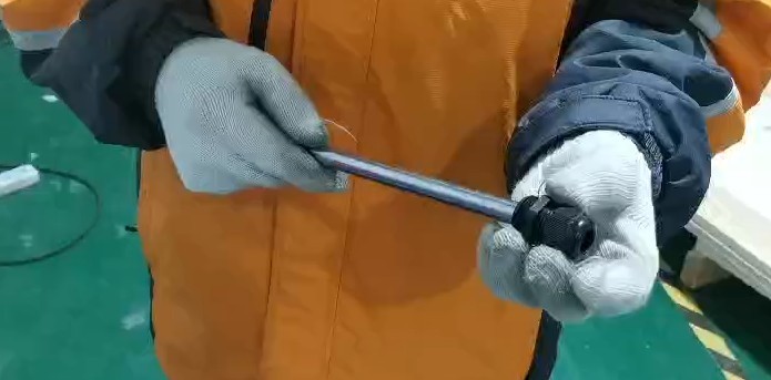
Figure 3
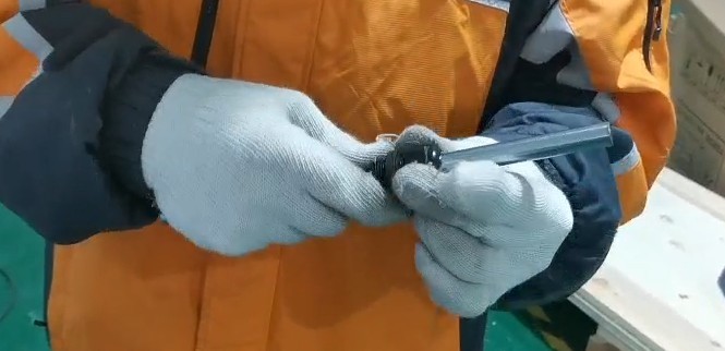
Figure 4
Loosen the three-jaw chuck fixtures on both sides.
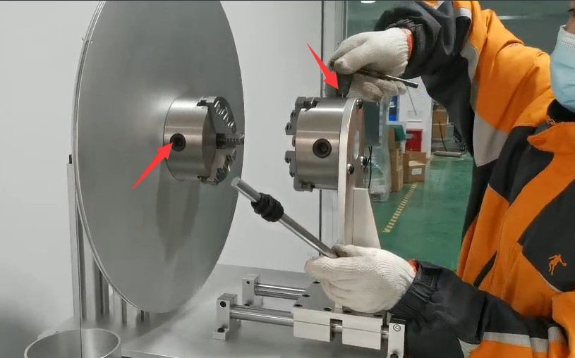
Figure 5
Insert the test rod and the sample so that the two parts of the sample are secured in the clamps on either side, and then retighten the three-jaw chuck to ensure there is no play.
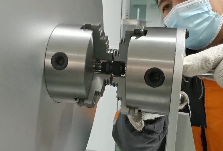
Figure 6
4.3 Installation and Calibration of Weights
Hang the weights on the steel cable along the rail at the edge of the disc, and place them inside the lifting platform.
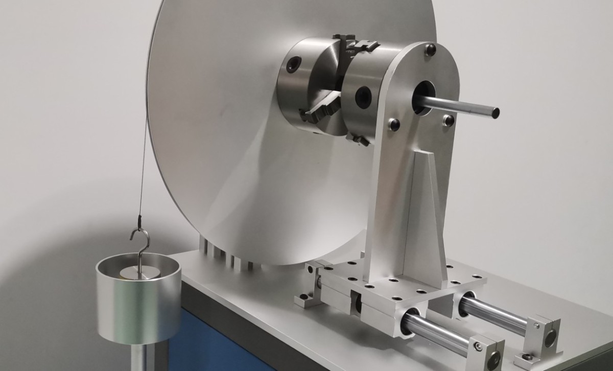
Figure 7
Note: Make sure the weights are not suspended in mid-air, and keep the steel wire rope as taut as possible.
4.4 Startup Test
Press the Reset button to clear the data from the previous test. Press the Start Test button, and the motorized lift will automatically lower; the torque generated by the weights and the disk will be applied to the sample, and the timer will begin counting.
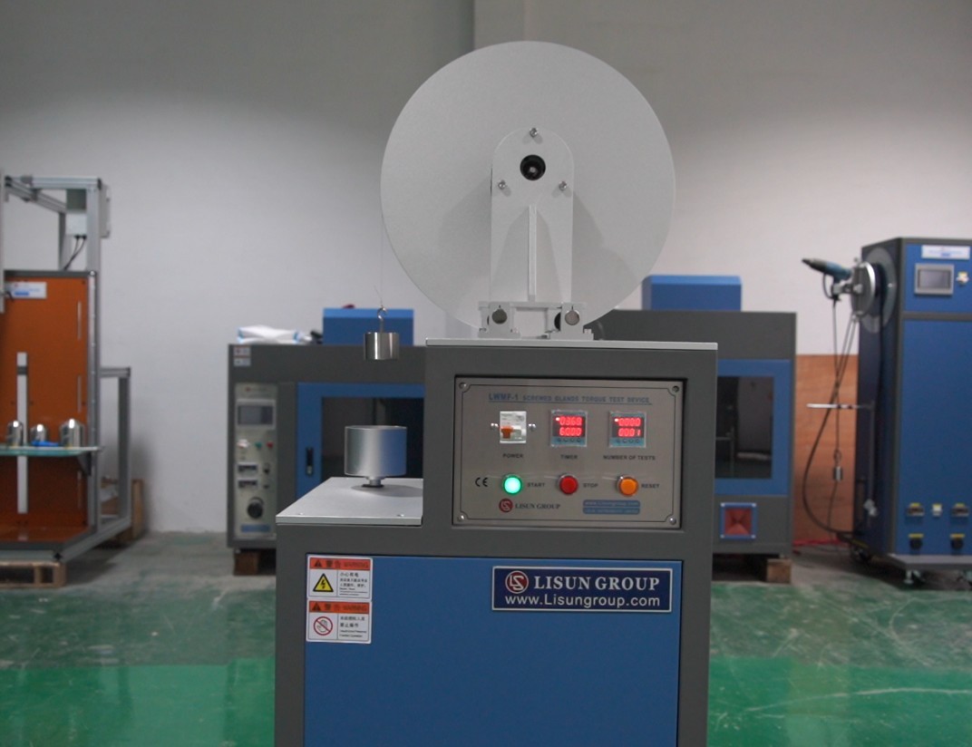
Figure 8
One minute later, the test ended, the electric lift platform rose automatically, the “Stop Test” button lit up, and the current test count was displayed as 1.
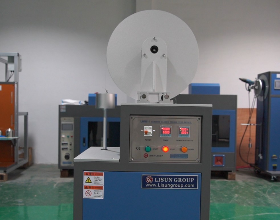
Figure 9
4.5 Evaluation of Test Results
In accordance with the requirements of the relevant national standards, a product is deemed to meet the requirements if it satisfies the following conditions:
The threaded sealing gland shows no damage, such as cracks, deformation, or stripped threads;
The specimen housing must not have any damage that does not meet the requirements of the standard;
No abnormal loosening or detachment occurred during the test.
5. Daily Maintenance and Care of Equipment
5.1 Cleaning and Maintenance
After the test is complete, wipe down the testing machine fixtures and other equipment with a dry cloth; do not use corrosive cleaning agents. Remove dust from the equipment’s terminal blocks to prevent poor contact.
5.2 Lubrication and Maintenance
Apply lubricating oil to the sliding and rotating parts of the test apparatus to ensure smooth mechanical operation.
Weights and test rods should be coated with rust-preventive oil on a regular basis to prevent rust and extend their service life.
5.3 Equipment Storage
5.3.1 Short-Term Storage Requirements
If the equipment is used on a daily basis, no further action is required after cleaning is completed following each test.
5.3.2 Requirements for Long-Term Storage
If the device will not be used for an extended period (more than one month), please disconnect all cables and cover the device with a dust cover to prevent dust buildup.
The device should be powered on once a month for just half an hour to prevent the aging of electrical components (such as capacitors and contactors).
6. Troubleshooting and Resolving Common Problems
6.1 Electrical System Malfunctions
6.1.1 Symptoms: The device will not power on; the display remains off.
Possible causes: Power is not connected, power cord is damaged, fuse is blown, power switch is faulty;
Troubleshooting: Check whether the power outlet is live, whether the power cord is damaged, and whether the plug is securely inserted. If the power switch is faulty and requires disassembly for internal repair, please contact LISUN Customer Service.
6.1.2 Symptom: Control panel buttons are unresponsive
Possible causes: Poor power connection, worn-out buttons, loose internal wiring;
Troubleshooting: Unplug the power cord, then plug it back in to restart the device; check the buttons for any foreign objects that might be causing them to stick, and clean the button surfaces; if the device still does not respond, contact customer service to have the buttons or internal wiring inspected and repaired.
6.2 Mechanical System Failures
6.2.1 Symptom: The fixture cannot secure the sample; it is loose.
Possible causes: Wear on the fixture jaws, loose adjustment screws, or a mismatch between the sample size and the test rod;
Solution: Check the clamping jaws of the fixture for wear; if they are severely worn, replace them. Tighten the set screws on the fixture’s adjustment threads to ensure smooth adjustment. Verify that the correct test rod has been selected (one with a diameter slightly smaller than the inner diameter of the O-ring and the nearest whole number).
6.2.2 Symptoms: The weights move jerkily and make unusual noises
Possible causes: lack of oil in the drive mechanism, tangled cable, or deformation of the weight cup;
Solution: After turning off the power, inspect the drive mechanism and apply a small amount of lubricating oil to the rotating shaft; straighten the ropes to ensure they are free of tangles or knots; if the ropes are severely worn, replace them; check the weight cup for deformation; if deformed, contact customer service to have it replaced.
6.3 Faults Caused by Abnormal Test Data
Problem Description: Samples are frequently damaged and do not meet expectations.
Possible causes: incorrect torque setting, improper selection of test rod, confusion regarding the applicable standard;
Solution: Double-check the sample type and the diameter of the test rod, and adjust the torque value according to the corresponding standard; verify that the correct test rod has been selected (with a diameter slightly smaller than the inner diameter of the seal and rounded to the nearest whole number); reconfirm the applicable national standard to avoid incorrect parameter settings.