
 English
 中文简体
中文简体 English
 Русский
 Español
 Português
 Türkçe
 العربية
 Deutsch
 Polski
 Italiano
 Français
 한국어
한국어 ไทย
ไทย Tiếng Việt
 日本語
日本語





























PWM Type AC Power Supply (Single Phase)
User's Manual
Applicable LISUN models: LSP-10KVAS、LSP-15KVAS、LSP-1KVAS、LSP-20KVAS、LSP-30KVAS、LSP-3KVAS、LSP-45KVAS、LSP-500VAS、LSP-5KVAS、LSP-60KVAS
1. Basic Understanding of Equipment
1.1 Key Technical Specifications
| Specifications/Model Numbers | LSP-500VAS, LSP-1KVAS, …… LSP-15KVAS |
| Capacity | 500 VA, 1 kVA, … 15 kVA |
| Circuit Configuration | (IGBT) Sine-Wave Pulse Width Modulation (SPWM) |
| Output Voltage | Single-phase, automatic range: 0–150 V / 150.1–300 V; high-range lock: 0–300 V |
| Maximum Output Current | 4.5A (low range)/2.25A (high range), 9A (low range)/4.5A (high range), … 136A (low range)/68A (high range) |
| Output Frequency | 45.00–70.00 Hz |
| Waveform Distortion | ≤1% (high/low voltage: 220 V/110 V ±15%, resistive load) |
1.2 Equipment Configuration Verification
1.2.1 Unpacking and Visual Inspection
When unpacking the device, handle it gently to avoid scratching the casing with sharp tools. After unpacking, first inspect the exterior of the device to ensure there are no obvious deformations or dents, and that the buttons are not damaged or loose. If you notice any abnormalities with the device or its accessories, do not turn it on. Please contact us immediately.
1.2.2 Main Unit and Accessories
| Number | Note |
| ① | LSP-VAS Series Power Supplies. Models LSP-2KVAS and below are desktop power supplies; models LSP-2KVAS and above are tower-style power supplies. |
| ② | Models LSP-2KVAS and below come with standard power cords; models above LSP-2KVAS feature terminal blocks, and users must wire them themselves. |
| ③ | RS-232 Communication Cable |
1.2.3 Downloading Electronic Documents
We have already sent the download links for the digital user manual, warranty card, and other documents via email at the time of shipment. Please download them as soon as possible. If you missed the email, you can also contact us to receive the download links again.
Note 1: Both the LISUN spectroradiometer and Goniophotomoeter software can control the LSP-VAS series power supplies; however, the LSP-VAS power supplies themselves do not come with dedicated software. Please operate them using the controls on the front panel of the device.
2. Safety Precautions
2.1 Electrical Safety Standards
Input power supply single-phase AC 220 V ±10 V, 50/60 Hz. It must comply with safety standards and be equipped with a proper protective grounding system, with a protective grounding resistance of ≤4 Ω, to prevent electric shock.
2.2 Environmental Safety Standards
For indoor use only; avoid direct sunlight. Place on a sturdy, stable surface to prevent severe vibrations. Ensure the environment is free of dust, corrosive gases, and flammable or explosive materials. Keep away from strong magnetic and electric fields. Ensure adequate ventilation; leave at least 10 cm of space around the device for heat dissipation, and do not block the exhaust vents of the cooling fans. Operating Environment: Temperature 5°C to 35°C, relative humidity ≤65% RH.
2.3 Operational Safety Guidelines
Do not operate the equipment or plug in/unplug the power cord with wet hands; Output must be shut off before connecting or disconnecting wires; do not touch the output terminals, internal components, the load, or load wiring while the equipment is operating; do not shut down the equipment directly while it is in output mode; shut off the output first before turning off the equipment; if you notice an unusual odor, smoke, abnormal noise, or overheating, immediately disconnect the power and do not continue operation.
3. Equipment Overview and Wiring
3.1 Introduction to the Front Panel
3.1.1 Desktop Power Supply
See Figure 3-1.
| Number | Note |
| ① | Power Switch |
| ② | Parameter Display Window. In standby mode, only the currently set voltage and frequency are displayed; in output mode, the current output voltage, frequency, current, and power are displayed; in output mode, pressing the Menu button toggles the display to show the power factor. |
| ③ | Voltage Setting Button |
| ④ | Frequency Setting Button |
| ⑤ | Menu button: Press this button in standby mode to configure system parameters such as current alarm thresholds, communication protocols, and baud rates. Note: If necessary, you can set a preset current alarm threshold; all other parameters should remain at their factory default values. |
| ⑥ | Output Key |
| ⑦ | Number Up and Down Keys |
| ⑧ | Shortcut Keys |
| ⑨ | Memory Key |
| ⑩ | High-End Locking Key |
| ⑪ | Keyboard Lock |
| ⑫ | Confirm Button/Reset Button |
| ⑬ | Rotary knob, which functions the same as the up and down arrow keys |
| ⑭ | Output outlet—please connect your AC load |
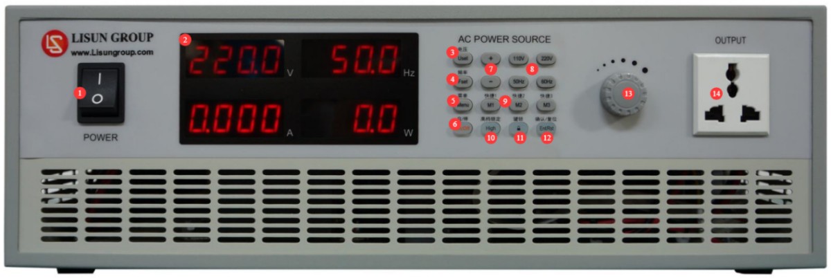
Figure 3-1
3.1.2 Vertical Power Supply
See Figure 3-2. Other than that, the front-panel operations are the same as those described in Section 3.1.1.
| Number | Note |
| ① | Power Switch |
| ② | Input power supply terminals: Please connect the device to a suitable power source. |
| ③ | Power output terminals—please connect your AC load here. |
| ④ | Output outlet: Please connect your AC load (loads of 10A or less only) |
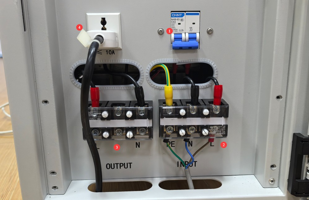
Figure 3-2
Note: The output wire gauge must be compatible with the AC load being connected.
3.2 Introduction to the Back Panel
3.2.1 Desktop Power Supply
See Figure 3-3.
| Number | Note |
| ① | The power cord receptacle includes a fuse to ensure the device is connected to an appropriate power source. |
| ② | Output outlet—please connect your AC load |
| ③ | RS232 communication port: If you need to use other software to control the power output, please connect it to your computer. |
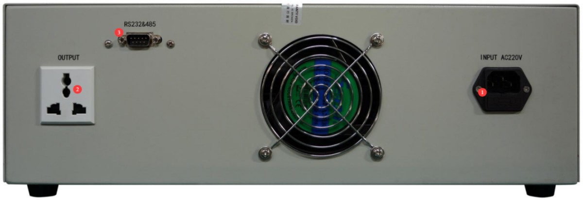
Figure 3-3
3.2.2 Vertical Power Supply
The rear panel of the vertical power supply has only one RS-232 communication port.
Equipment Operation
4.1 Routine Operations
| Instructions | Note |
| ① | Confirm whether high-range lock is required. Automatic mode: 0–150 V / 150.1–300 V, continuously adjustable; High-range lock: 0–300 V, continuously adjustable |
| ② | If necessary, refer to Section 3.1.1 to set the current alarm threshold. When the power supply is active, if the output current reaches the set current alarm threshold, the output will automatically be cut off and an alarm will sound; press the reset button to clear the alarm. |
| ③ | Use the voltage setting button, frequency setting button, quick-set button, value increase/decrease buttons, and knob to set the output voltage and frequency. |
| ④ | Press the Output button to start output. |
| ⑤ | In output mode, you can use the numeric up and down keys or the knob to continue adjusting the output voltage. |
| ⑥ | Press the output button again to stop the output. |
4.2 Using the Memory Keys
The device can store three sets of data—M1, M2, and M3—to enable quick setup and output. Let’s take M1 as an example.
| Instructions | Note |
| ① | In standby mode, press and hold the M1 button for 5 seconds to enter the voltage settings menu and set the desired output voltage. |
| ② | Press the M1 button again to enter the frequency settings and set the desired output frequency. |
| ③ | Press the M1 key again to save and exit. |
| ④ | Press the M1 key to retrieve the saved data. |
| ⑤ | Press the Output button to start output; while in output mode, use the up and down number buttons or the knob to continue adjusting the output voltage; press the Output button again to stop the output. |
5. Daily Maintenance and Care of Equipment
5.1 Routine Maintenance
5.1.1 Daily Cleaning
Be sure to turn off the power and unplug the power cord before cleaning. We recommend wiping the device with a soft, anti-static cotton cloth and a mild detergent; do not spray liquids directly onto the device. Do not use chemical solvents such as benzene, toluene, or acetone.
5.1.2 Routine Inspections
Before each use, check that the power cord and terminal connections are secure and free of burn marks; ensure that the fan vents are not blocked; and after turning on the unit, verify that the indicator lights and display are functioning properly.
5.2 Storage Specifications
5.2.1 Storage Environment Requirements
Temperature: 5°C to 35°C; relative humidity: ≤65% RH; dry, dust-free environment free of corrosive gases.
5.2.2 Long-Term Storage Operations
Turn off the power and unplug all cables; clean the equipment and wrap it in dust-proof film; turn on the power for 10 minutes each month to prevent moisture damage to the components.
5.3 Calibration Interval Requirements
To ensure the measurement accuracy and operational reliability of the equipment, it is recommended that it be sent periodically to a qualified third-party metrology organization for calibration. The recommended calibration interval is 12 months. Users may determine the specific calibration interval based on frequency of use, environmental conditions, and quality system requirements.
6. Troubleshooting and Resolving Common Problems
| Fault Symptoms | Possible Causes | Procedure |
| Unable to Power On | Input power supply failure, blown fuse | Check Input power supply; check the fuse. If it has blown, replace it with a fuse of the same rating. Do not use a fuse with a higher current rating. |
| The output voltage cannot be continuously adjusted | Gear Shift Issues | If the high-range lock button is not used, the unit operates in automatic mode, with a maximum output voltage of 150 V in low range and a minimum output voltage of 150.1 V in high range. |
| Alarm during output | The load exceeds the power supply’s capacity | For example, the LSP-500VAS has a maximum capacity of 500VA; do not connect loads that exceed the power supply’s capacity. |
| The fan isn’t spinning | Dust buildup, motor malfunction | Turn off the power and clean the dust from the fan; if the problem persists, please contact us for repair or to have the fan replaced. |
7. Packing List
| No. | Name | Quantity |
| ① | LSP-*VAS Series Power Supply Units | 1 unit |
| ② | Power Cord (Standard power cords are included only with the LSP-2KVAS and lower models) | 1 piece |
| ③ | RS-232 Communication Cable |